4-12
Upgrading Your System
7.
Remove the new processor from its antistatic package and place it on a grounded,
static-free surface or conductive foam pad.
8.
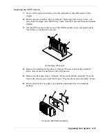
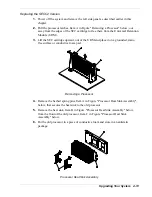
Position the heat sink, Item C in Figure "Processor Heat Sink Assembly" above, on
the front of the new processor so that the holes in the heat sink line up with the
holes in the processor.
9.
Install the attachment clip, Item A in Figure "Processor Heat Sink Assembly"
above, that secures the heat sink to the processor.
10.
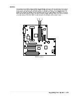
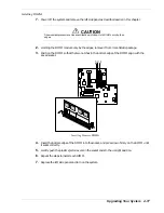
Position the processor back into the URM. Ensure that the alignment notch in the
SEPP board fits over the plug in Slot 1. Push down firmly, with even pressure on
both sides of the top, until the SEPP board is seated.
11.
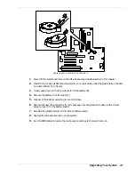
To lock in the processor, push the latches inward until they secure the SEPP board
into place in the URM, Item A in Figure "Removing a Processor" above. The
latches must be secured for proper electrical connection of the processor.
12.
After you have installed a new processor, you must run the BIOS Setup Utility (F2)
to configure its speed. Refer to Chapter 3, “Configuring Your System.”
13.
Replace the left side panel and power up the system.
Summary of Contents for EXPRESS 5800 ES1400 SERIES Online
Page 1: ...EXPRESS5800 ES1400 SERIES ONLINE SERVICE GUIDE...
Page 8: ...Using This Guide xv...
Page 21: ......
Page 33: ...2 12 Setting Up the System...
Page 60: ...Configuring Your System 3 27...
Page 130: ...Problem Solving 5 21...
Page 131: ......
Page 132: ......
Page 142: ...6 10 Illustrated Parts Breakdown...
Page 149: ...System Cabling A 7 WIDE SCSI CABLE 68 pins IDE CABLE 40 pins Standard System Cable Routing...
Page 160: ...System Setup Utility B 9 Adding and Removing ISA Cards Window...
Page 163: ...B 12 System Setup Utility System Resource Usage Window...


