Upgrading Your System 4-49
Replacing the Intrusion Switch
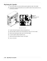
1.
Power off the system and remove the left side panel as described earlier in this chapter.
2.
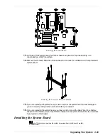
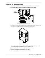
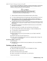
Tag and disconnect the intrusion switch cable from the system board connector.
Intrusion
Alarm
Connector
Intrusion Alarm Switch Cable Connection
3.
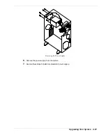
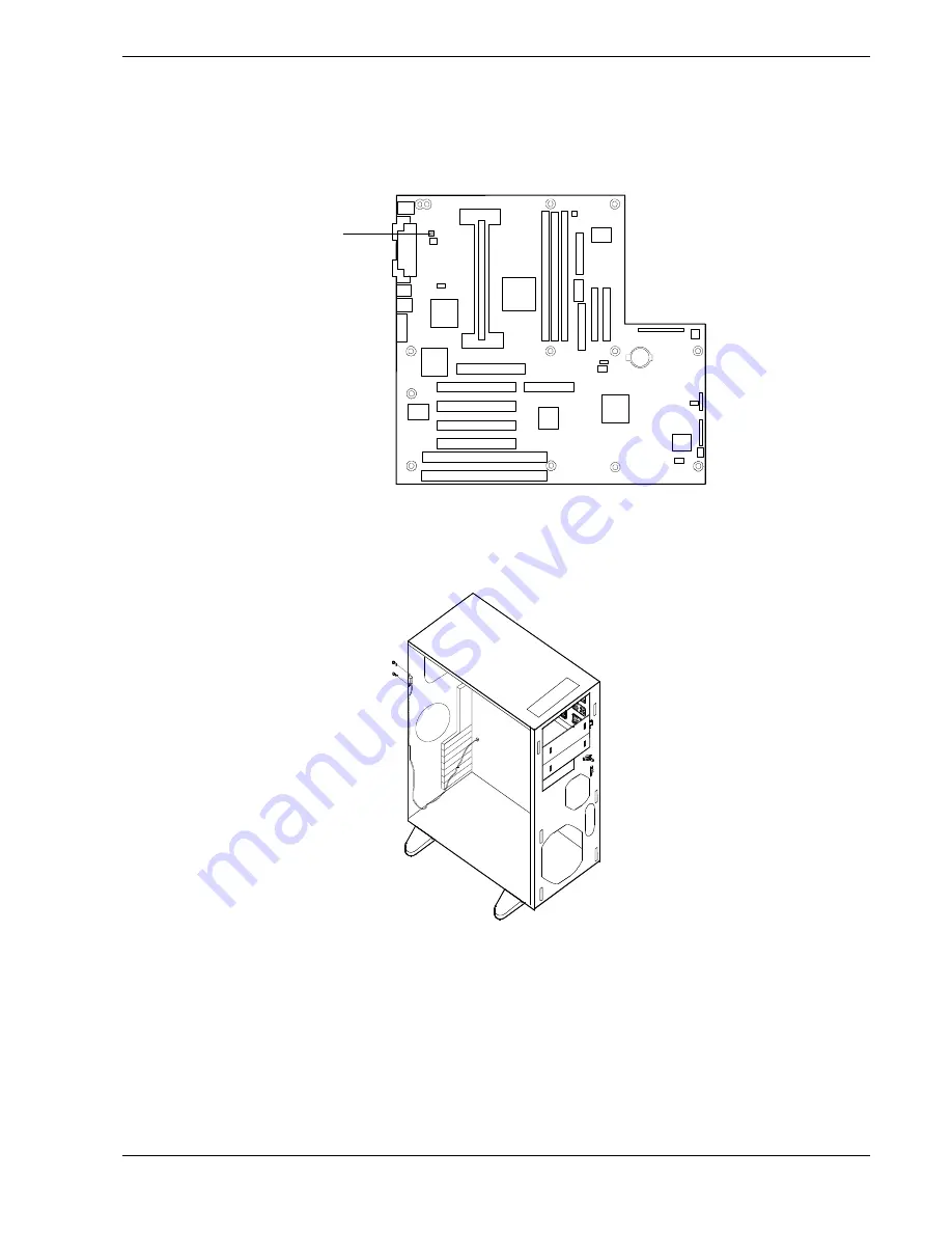
Using a small Phillips-head screwdriver, remove the two screws securing the intrusion switch
to the rear of the chassis. Remove the intrusion switch and cable assembly.
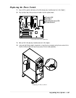
Replacing the power Switch
4.
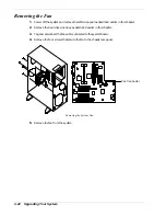
Position the replacement intrusion alarm switch behind the rear of the chassis and secure it
with two Phillips-head screws inserted through the rear of the chassis.
5.
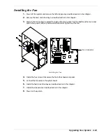
Connect the intrusion alarm switch cable to the system board connector.
6.
Install the left side panel as described earlier in this chapter.
7.
Power on the system.
Summary of Contents for EXPRESS 5800 ES1400 SERIES Online
Page 1: ...EXPRESS5800 ES1400 SERIES ONLINE SERVICE GUIDE...
Page 8: ...Using This Guide xv...
Page 21: ......
Page 33: ...2 12 Setting Up the System...
Page 60: ...Configuring Your System 3 27...
Page 130: ...Problem Solving 5 21...
Page 131: ......
Page 132: ......
Page 142: ...6 10 Illustrated Parts Breakdown...
Page 149: ...System Cabling A 7 WIDE SCSI CABLE 68 pins IDE CABLE 40 pins Standard System Cable Routing...
Page 160: ...System Setup Utility B 9 Adding and Removing ISA Cards Window...
Page 163: ...B 12 System Setup Utility System Resource Usage Window...

