4-40
Upgrading Your System
1.
Remove both side panels as described earlier in this chapter.
2.
Remove top panel as described earlier in this chapter.
CAUTION
Observe static precautions
3.
Install the Processor Retention Module removed from the original system board and configure
the system board jumpers on the new board before you install it.
4.
If this is a replacement system board, install the Real-Time Clock battery, the Pentium II
Processor(s) and any DIMMs removed from the original system board. Refer to procedures
found earlier in this chapter.
5.
Remove the hard disk drive bay as described earlier in this chapter (if not already completed
earlier).
6.
Remove the removable media drive bay (if not already completed earlier).
7.
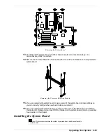
Install the system board into the chassis and secure with the mounting screws.
8.
Connect the fan cable speaker cable and to the system board.
9.
Connect the front panel switch and LED cables to the system board.
10.
Connect the external cables to the I/O connectors.
11.
Connect the power cables to the system board.
12.
Connect the interface and controller cables to the system board.
13.
Install any option boards removed.
Note:
The option boards must be reinstalled in the same slots
when you reassemble the system.
14.
Install the hard disk drive bay and removable media drive bay.
15.
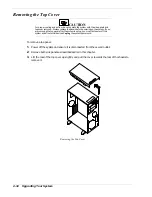
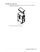
Install the top cover as described earlier in this chapter.
16.
Install the side panels as described earlier in this chapter and power on the system.
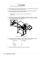
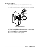
Replacing the Power Supply
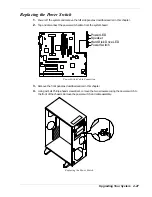
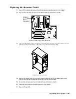
1.
Power off the system and remove the left side panel as described earlier in this chapter.
2.
Remove the hard disk drive bay as described earlier in this chapter.
3.
Tag and disconnect power cables connected to the system board.
4.
Tag and disconnect the power cables connected to all internal peripheral devices.
5.
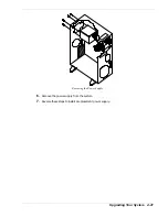
Support the bottom of the power supply and remove the four screws that secure the power
supply to the rear panel.
Summary of Contents for EXPRESS 5800 ES1400 SERIES Online
Page 1: ...EXPRESS5800 ES1400 SERIES ONLINE SERVICE GUIDE...
Page 8: ...Using This Guide xv...
Page 21: ......
Page 33: ...2 12 Setting Up the System...
Page 60: ...Configuring Your System 3 27...
Page 130: ...Problem Solving 5 21...
Page 131: ......
Page 132: ......
Page 142: ...6 10 Illustrated Parts Breakdown...
Page 149: ...System Cabling A 7 WIDE SCSI CABLE 68 pins IDE CABLE 40 pins Standard System Cable Routing...
Page 160: ...System Setup Utility B 9 Adding and Removing ISA Cards Window...
Page 163: ...B 12 System Setup Utility System Resource Usage Window...

