Upgrading Your System 4-19
Option Boards
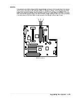
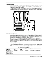
This section describes how to install and remove ISA and PCI option boards. The system board has
two ISA bus expansion slots and four PCI bus expansion slots. One of the ISA connectors shares a
chassis expansion slot with a PCI connector.
The high-performance PCI local bus allows the adoption of newer networking technology, such as
100 MB/second Ethernet NICs, with a minimum of effort and without concern for I/O bottlenecks.
The PCI local bus offers up to 133 MB/second bandwidth.
ISA 2
ISA 1
PCI 1
PCI 2
PCI 3
PCI 4
PCI and ISA Slot Locations
Installation Considerations
Newer adapters, designed for Plug-and-Play systems, are automatically configured by the system
without any user intervention. Older ISA adapters must be manually configured as detailed below.
Once the manual configuration is complete, the Plug-and-Play adapters are configured around the
manually configured adapters without causing any resource conflicts.
ISA adapters can be Plug-and-Play. ISA adapters that are not Plug-and-Play must be manually
configured following the instructions supplied with the board. The configuration is defined to the
system by creating the ISA configuration file when running the SSU. If you are adding a non-Plug
and Play ISA option board, run the SSU before installing the board. For details on running the SSU,
refer to Appendix B.
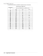
Controller/Adapter Hardware Configurations
This table lists the option boards you may add to your system that require specific installation slots
and provides information on memory and I/O addressing and assigned interrupt request number
(IRQ).
Option Board Hardware Configurations
Option Board
IRQ
Memory
Address
I/O Address
Option Slot
NEC SecuRAID 110
(
Mylex AcceleRAID 150)
NEC SecuRAID 210
(
Mylex AcceleRAID 250)
Set by BIOS
Set by BIOS
Set by BIOS
PCI Slot 2 (see PCI/ISA Slot Location
illustration above)
Summary of Contents for EXPRESS 5800 ES1400 SERIES Online
Page 1: ...EXPRESS5800 ES1400 SERIES ONLINE SERVICE GUIDE...
Page 8: ...Using This Guide xv...
Page 21: ......
Page 33: ...2 12 Setting Up the System...
Page 60: ...Configuring Your System 3 27...
Page 130: ...Problem Solving 5 21...
Page 131: ......
Page 132: ......
Page 142: ...6 10 Illustrated Parts Breakdown...
Page 149: ...System Cabling A 7 WIDE SCSI CABLE 68 pins IDE CABLE 40 pins Standard System Cable Routing...
Page 160: ...System Setup Utility B 9 Adding and Removing ISA Cards Window...
Page 163: ...B 12 System Setup Utility System Resource Usage Window...


