Setting Up the System 2-5
Rear View
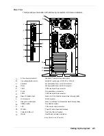
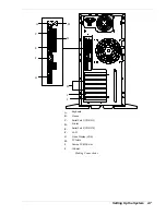
This figure shows the location of the following rear system controls and indicators.
115V
A
B
D
H
M
J
N
O
C
E
F
G
I
K
L
A.
AC input power connector
Supplies AC power to the power supply.
B.
Line voltage selector switch
Selects AC input power of 115 VAC or 230 VAC.
C.
Keyboard
PS/2-compatible 6-pin mini-DIN connector.
D.
Mouse
PS/2-compatible 6-pin mini-DIN connector.
E.
COM1
COM1 serial port 9-pin connector.
F.
Printer
25-pin parallel port connector.
G.
COM2
COM2 serial port 9-pin connector.
H.
Green LAN status light
When lit, LAN is linked to network (see following table).
I.
LAN connector
RJ-45 Connector
J.
Orange LAN status light
When lit, 100 Mbps LAN connection (see following table).
K.
USB connectors
Two USB Connectors.
L.
VGA
VGA monitor 15-pin connector.
M.
PCI slots
Three PCI add-in board slot locations.
N.
Combo PCI/ISA slot
One PCI or ISA slot location.
O.
ISA slot
One ISA add-in board slot location.
Rear Features and Controls
Summary of Contents for EXPRESS 5800 ES1400 SERIES Online
Page 1: ...EXPRESS5800 ES1400 SERIES ONLINE SERVICE GUIDE...
Page 8: ...Using This Guide xv...
Page 21: ......
Page 33: ...2 12 Setting Up the System...
Page 60: ...Configuring Your System 3 27...
Page 130: ...Problem Solving 5 21...
Page 131: ......
Page 132: ......
Page 142: ...6 10 Illustrated Parts Breakdown...
Page 149: ...System Cabling A 7 WIDE SCSI CABLE 68 pins IDE CABLE 40 pins Standard System Cable Routing...
Page 160: ...System Setup Utility B 9 Adding and Removing ISA Cards Window...
Page 163: ...B 12 System Setup Utility System Resource Usage Window...

