Issue 6
Electra Elite
7 - 28
Installing Optional Equipment
2.
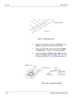
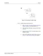
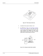
Remove the display plate from DBM(B)/(E) and
DBM(E), and peel off the cover sheet on both.
3.
Insert protruding side of the cable from the DBM(E)
in DBM(B) CN7 or in CN7 of the previous DBM(E).
4.
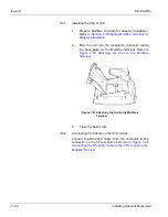
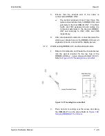
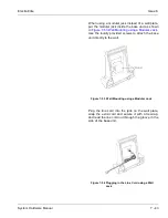
Slide the bracket on DBM(E) being installed into the
groves on DBM(B)/(E) and tighten the nuts and
bolts. Refer to
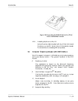
Figure 7-34 Connecting the Bracket
.
Figure 7-33 Removing Cutout
Figure 7-34 Connecting the Bracket
Summary of Contents for Electra Elite 192
Page 2: ...SYSTEM HARDWARE MANUAL Stock Number 750363 Issue 6 Series 6000 192 ...
Page 3: ......
Page 5: ......
Page 9: ...THIS PAGE INTENTIONALLY LEFT BLANK ...
Page 10: ...Regulatory Information ...
Page 11: ......
Page 20: ......
Page 52: ...Issue 6 Electra Elite xxxii List of Tables THIS PAGE INTENTIONALLY LEFT BLANK ...
Page 73: ...Electra Elite Issue 6 System Hardware Manual 1 21 THIS PAGE INTENTIONALLY LEFT BLANK ...
Page 74: ...Issue 6 Electra Elite 1 22 Introduction ...
Page 96: ...Issue 6 Electra Elite 2 22 System Specifications ...
Page 104: ...Issue 6 Electra Elite 3 8 Hardware Requirements THIS PAGE INTENTIONALLY LEFT BLANK ...
Page 213: ...Electra Elite Issue 6 System Hardware Manual 5 67 Figure 5 39 FMS 8 U10 ETU ...
Page 336: ...Issue 6 Electra Elite 7 54 Installing Optional Equipment THIS PAGE INTENTIONALLY LEFT BLANK ...
Page 368: ...Issue 6 Electra Elite A 4 Glossary of Abbreviations THIS PAGE INTENTIONALLY LEFT BLANK ...
Page 369: ...SYSTEM HARDWARE MANUAL NEC America Inc Issue 6 Series 6000 192 ...

