Issue 6
Electra Elite
5 - 56
Installing Electronic Telephone Units
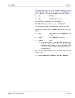
D
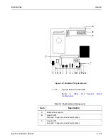
Port Expansion Board (PEB) cable
E
Modem connector
F
Hard Drive (HD) LED
G
Universal Serial Bus (USB) connector
H
Local-Area Network (LAN) connector
I
Keyboard connector
J
Mouse connector
K
COM Serial Port connector
L
VGA Monitor connector
M
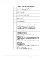
Switch SW3
DIP switch 1 default is Off so the voice messaging application starts
when the board is turned On. Set this switch On to start OS/2
software only.
DIP switch 2 default is Off for direct serial remote access
connections. Set this switch On for modem connections.
DIP switches 3 and 4 are not used and should be left On.
N
Power button. It cuts the power to the board from the PC and the
hard drive and should not be used.
O
Voice messaging software LED.
Green when software is active
Amber when active with possible application problem
Red when inactive or shut down
P
Shutdown switch
Default is On. Place Off to shut down the software and system board
properly before turning off the telephone system and disconnecting
the system board.
Place On before restarting – The board restarts only when the switch
is On.
Q
Shutdown LED
Red when switch is On
Green when switch is Off
After the LED goes off, turn off power to the KSU and disconnect the
board.
R
Make Busy switch and LED
Do not use. Must always be On with a red LED.
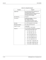
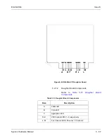
Table 5-14 System Board Components (Continued)
Item
Description
Summary of Contents for Electra Elite 192
Page 2: ...SYSTEM HARDWARE MANUAL Stock Number 750363 Issue 6 Series 6000 192 ...
Page 3: ......
Page 5: ......
Page 9: ...THIS PAGE INTENTIONALLY LEFT BLANK ...
Page 10: ...Regulatory Information ...
Page 11: ......
Page 20: ......
Page 52: ...Issue 6 Electra Elite xxxii List of Tables THIS PAGE INTENTIONALLY LEFT BLANK ...
Page 73: ...Electra Elite Issue 6 System Hardware Manual 1 21 THIS PAGE INTENTIONALLY LEFT BLANK ...
Page 74: ...Issue 6 Electra Elite 1 22 Introduction ...
Page 96: ...Issue 6 Electra Elite 2 22 System Specifications ...
Page 104: ...Issue 6 Electra Elite 3 8 Hardware Requirements THIS PAGE INTENTIONALLY LEFT BLANK ...
Page 213: ...Electra Elite Issue 6 System Hardware Manual 5 67 Figure 5 39 FMS 8 U10 ETU ...
Page 336: ...Issue 6 Electra Elite 7 54 Installing Optional Equipment THIS PAGE INTENTIONALLY LEFT BLANK ...
Page 368: ...Issue 6 Electra Elite A 4 Glossary of Abbreviations THIS PAGE INTENTIONALLY LEFT BLANK ...
Page 369: ...SYSTEM HARDWARE MANUAL NEC America Inc Issue 6 Series 6000 192 ...


