Issue 6
Electra Elite
xxvi
List of Figures
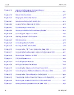
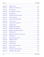
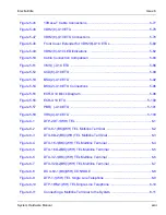
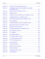
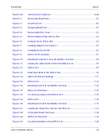
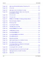
Figure 7-25
Attaching an Electra Elite Multiline Terminal to a PC ................................. 7-21
Figure 7-26
CTA-U Unit ................................................................................................. 7-21
Figure 7-27
Attaching the Unit to the Multiline Terminal ................................................ 7-22
Figure 7-28
Connecting the RS-232C Cable to the CTA-U Unit
on the Multiline Terminal .............................................................................7-23
Figure 7-29
CTU (C)-U Unit ........................................................................................... 7-24
Figure 7-30
CTU (S)-U Unit ........................................................................................... 7-25
Figure 7-31
DBM(B)-U10 & DBM(E)-U10 Message Display Boards ............................. 7-26
Figure 7-32
Maximum Display Indications ..................................................................... 7-27
Figure 7-33
Removing Cutout .......................................................................................7-28
Figure 7-34
Connecting the Bracket .............................................................................. 7-28
Figure 7-35
Threading Screw into Wall ......................................................................... 7-29
Figure 7-36
Hanging DBM(B)-U10 on Screw ................................................................ 7-30
Figure 7-37
Installing Bottom Screws ............................................................................ 7-30
Figure 7-38
Connecting DBM(B)-U10 ........................................................................... 7-31
Figure 7-39
Connecting DBM(B)-U10 to ESI Port ......................................................... 7-32
Figure 7-40
HFU-U(BK)/(WH) Unit ................................................................................ 7-32
Figure 7-41
Microphone with Mute ................................................................................ 7-33
Figure 7-42
Attaching a Microphone to a Multiline Terminal ......................................... 7-33
Figure 7-43
HFU-U(BK)/(WH) Unit Switches ................................................................. 7-34
Figure 7-44
Connecting a Single Line Telephone to the System
using an SLT(1)-U10 ADP .......................................................................... 7-36
Figure 7-45
Connecting the SLT(1)-U10 ADP ............................................................... 7-37
Figure 7-46
Removing the Screws from the SLT(1)-U10 ADP ...................................... 7-38
Figure 7-47
Attaching the SLT(1)-U10 ADP to the Wall ................................................ 7-38
Figure 7-48
VDD-U Unit ................................................................................................7-39
Summary of Contents for Electra Elite 192
Page 2: ...SYSTEM HARDWARE MANUAL Stock Number 750363 Issue 6 Series 6000 192 ...
Page 3: ......
Page 5: ......
Page 9: ...THIS PAGE INTENTIONALLY LEFT BLANK ...
Page 10: ...Regulatory Information ...
Page 11: ......
Page 20: ......
Page 52: ...Issue 6 Electra Elite xxxii List of Tables THIS PAGE INTENTIONALLY LEFT BLANK ...
Page 73: ...Electra Elite Issue 6 System Hardware Manual 1 21 THIS PAGE INTENTIONALLY LEFT BLANK ...
Page 74: ...Issue 6 Electra Elite 1 22 Introduction ...
Page 96: ...Issue 6 Electra Elite 2 22 System Specifications ...
Page 104: ...Issue 6 Electra Elite 3 8 Hardware Requirements THIS PAGE INTENTIONALLY LEFT BLANK ...
Page 213: ...Electra Elite Issue 6 System Hardware Manual 5 67 Figure 5 39 FMS 8 U10 ETU ...
Page 336: ...Issue 6 Electra Elite 7 54 Installing Optional Equipment THIS PAGE INTENTIONALLY LEFT BLANK ...
Page 368: ...Issue 6 Electra Elite A 4 Glossary of Abbreviations THIS PAGE INTENTIONALLY LEFT BLANK ...
Page 369: ...SYSTEM HARDWARE MANUAL NEC America Inc Issue 6 Series 6000 192 ...

