Electra Elite
Issue 6
System Hardware Manual
7 - 19
3.4.2
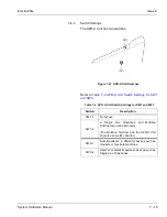
Switch Settings
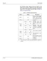
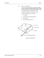
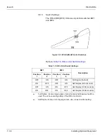
The APR-U Unit has two switches.
Refer to
Table 7-4 APR-U Unit Switch Settings for SW1
and SW3
.
Figure 7-23 APR-U Unit Switches
Table 7-4 APR-U Unit Switch Settings for SW1 and SW3
Switch
Description
SW1–1
Do not use
SW1–2
A Single Line Telephone and Multiline
Terminal are used alternately.
(The Multiline Terminal and the APR-U Unit
share the same B1 channel.)
SW3–1
Sets impedance to 600
Ω
for devices such as
modems or facsimile machines.
SW3–2
Used for complex impedance devices such as
Single Line Telephones.
Summary of Contents for Electra Elite 192
Page 2: ...SYSTEM HARDWARE MANUAL Stock Number 750363 Issue 6 Series 6000 192 ...
Page 3: ......
Page 5: ......
Page 9: ...THIS PAGE INTENTIONALLY LEFT BLANK ...
Page 10: ...Regulatory Information ...
Page 11: ......
Page 20: ......
Page 52: ...Issue 6 Electra Elite xxxii List of Tables THIS PAGE INTENTIONALLY LEFT BLANK ...
Page 73: ...Electra Elite Issue 6 System Hardware Manual 1 21 THIS PAGE INTENTIONALLY LEFT BLANK ...
Page 74: ...Issue 6 Electra Elite 1 22 Introduction ...
Page 96: ...Issue 6 Electra Elite 2 22 System Specifications ...
Page 104: ...Issue 6 Electra Elite 3 8 Hardware Requirements THIS PAGE INTENTIONALLY LEFT BLANK ...
Page 213: ...Electra Elite Issue 6 System Hardware Manual 5 67 Figure 5 39 FMS 8 U10 ETU ...
Page 336: ...Issue 6 Electra Elite 7 54 Installing Optional Equipment THIS PAGE INTENTIONALLY LEFT BLANK ...
Page 368: ...Issue 6 Electra Elite A 4 Glossary of Abbreviations THIS PAGE INTENTIONALLY LEFT BLANK ...
Page 369: ...SYSTEM HARDWARE MANUAL NEC America Inc Issue 6 Series 6000 192 ...

