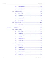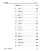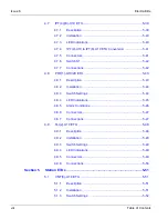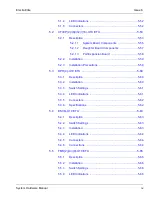
Issue 6
Electra Elite
xx
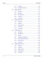
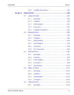
List of Figures
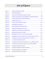
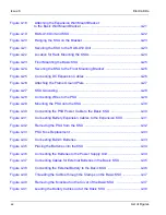
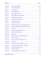
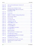
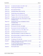
Figure 4-18
Attaching the Expansion Wall Mount Bracket
to the Basic Wall Mount Bracket ................................................................. 4-21
Figure 4-19
RAK-U10 Unit and KSU .............................................................................4-22
Figure 4-20
Hanging the KSU on the Bracket ............................................................... 4-23
Figure 4-21
Securing the KSU to the RAK-U10 Unit ..................................................... 4-23
Figure 4-22
Location for Rack Mounting the KSUs ....................................................... 4-24
Figure 4-23
Floor Mounting the Basic KSU ...................................................................4-25
Figure 4-24
Securing the KSU to the Floor Mounting Bracket ...................................... 4-26
Figure 4-25
Connecting DC Expansion Cables ............................................................. 4-26
Figure 4-26
Attaching the Frame Ground Plate ............................................................. 4-27
Figure 4-27
KSU Grounding .......................................................................................... 4-28
Figure 4-28
Connecting Wires to the PSU ....................................................................4-29
Figure 4-29
Mounting the PSU onto the KSU ................................................................ 4-30
Figure 4-30
Connecting the PSU Power Cable to the Basic KSU ................................. 4-30
Figure 4-31
Connecting Battery Expansion Cables to the Expansion KSU .................. 4-31
Figure 4-32
Removing the PSU from the KSU .............................................................. 4-32
Figure 4-33
PSU Fuse Replacement .............................................................................4-33
Figure 4-34
Connecting Built-In Batteries ...................................................................... 4-33
Figure 4-35
Placing the Batteries into the KSU ............................................................. 4-34
Figure 4-36
Connecting the Batteries to the Power Supply Unit ................................... 4-34
Figure 4-37
Connecting Cables for External Batteries in the Basic KSU ...................... 4-35
Figure 4-38
Connecting the External Battery to the Basic KSU .................................... 4-36
Figure 4-39
Threading the Cables through the Clamps on the Basic KSU ................... 4-37
Figure 4-40
Removing the Knockout on the Cover of the Basic KSU ........................... 4-37
Figure 4-41
Leading the Battery Cables out of the Basic KSU ...................................... 4-38
Summary of Contents for Electra Elite 192
Page 2: ...SYSTEM HARDWARE MANUAL Stock Number 750363 Issue 6 Series 6000 192 ...
Page 3: ......
Page 5: ......
Page 9: ...THIS PAGE INTENTIONALLY LEFT BLANK ...
Page 10: ...Regulatory Information ...
Page 11: ......
Page 20: ......
Page 52: ...Issue 6 Electra Elite xxxii List of Tables THIS PAGE INTENTIONALLY LEFT BLANK ...
Page 73: ...Electra Elite Issue 6 System Hardware Manual 1 21 THIS PAGE INTENTIONALLY LEFT BLANK ...
Page 74: ...Issue 6 Electra Elite 1 22 Introduction ...
Page 96: ...Issue 6 Electra Elite 2 22 System Specifications ...
Page 104: ...Issue 6 Electra Elite 3 8 Hardware Requirements THIS PAGE INTENTIONALLY LEFT BLANK ...
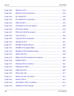
Page 213: ...Electra Elite Issue 6 System Hardware Manual 5 67 Figure 5 39 FMS 8 U10 ETU ...
Page 336: ...Issue 6 Electra Elite 7 54 Installing Optional Equipment THIS PAGE INTENTIONALLY LEFT BLANK ...
Page 368: ...Issue 6 Electra Elite A 4 Glossary of Abbreviations THIS PAGE INTENTIONALLY LEFT BLANK ...
Page 369: ...SYSTEM HARDWARE MANUAL NEC America Inc Issue 6 Series 6000 192 ...

