


Issue 6
Electra Elite
4 - 10
Installing KSUs
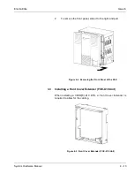
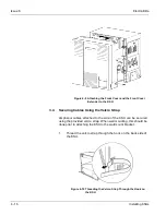
2.5
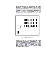
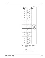
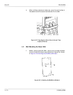
Power Failure Transfer
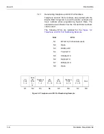
The Power Failure Transfer relay is located in the KSU. When
selecting a Single Line Telephone for power failure transfer, make
sure it matches the CO line dialing type (10 pps, 20 pps, or DTMF)
where it is connected. A Single Line Telephone with a ground
button must be used with Ground Start Trunks.
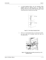
Figure 4-2 Power
Failure Transfer Connections
is a relay diagram. The relay is shown
with the power ON.
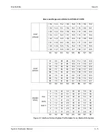
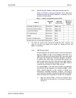
3 PFT Circuits for each B64-U10 KTU
Figure 4-2 Power Failure Transfer Connections
M
D
F
M
D
F
C
O
I
S
L
I
Relay 1
Tip
Ring
Tip
Ring
T
E
L
C
O
SLT
Summary of Contents for Electra Elite 192
Page 2: ...SYSTEM HARDWARE MANUAL Stock Number 750363 Issue 6 Series 6000 192 ...
Page 3: ......
Page 5: ......
Page 9: ...THIS PAGE INTENTIONALLY LEFT BLANK ...
Page 10: ...Regulatory Information ...
Page 11: ......
Page 20: ......
Page 52: ...Issue 6 Electra Elite xxxii List of Tables THIS PAGE INTENTIONALLY LEFT BLANK ...
Page 73: ...Electra Elite Issue 6 System Hardware Manual 1 21 THIS PAGE INTENTIONALLY LEFT BLANK ...
Page 74: ...Issue 6 Electra Elite 1 22 Introduction ...
Page 96: ...Issue 6 Electra Elite 2 22 System Specifications ...
Page 104: ...Issue 6 Electra Elite 3 8 Hardware Requirements THIS PAGE INTENTIONALLY LEFT BLANK ...
Page 213: ...Electra Elite Issue 6 System Hardware Manual 5 67 Figure 5 39 FMS 8 U10 ETU ...
Page 336: ...Issue 6 Electra Elite 7 54 Installing Optional Equipment THIS PAGE INTENTIONALLY LEFT BLANK ...
Page 368: ...Issue 6 Electra Elite A 4 Glossary of Abbreviations THIS PAGE INTENTIONALLY LEFT BLANK ...
Page 369: ...SYSTEM HARDWARE MANUAL NEC America Inc Issue 6 Series 6000 192 ...


