Issue 6
Electra Elite
5 - 72
Installing Electronic Telephone Units
5.6.2
Installation
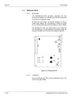
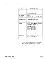
A maximum of 22 OPX(2)-U10 ETUs can be installed in
slots S1~S8 in any system KSU. The extension can be
run up to three miles (5 km) using 24 AWG wiring.
5.6.3
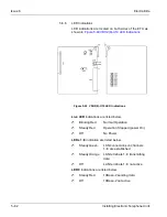
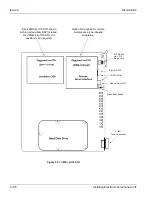
LED Indications
Live LED indications are listed below.
Blinking Red
Normal Operation
Steady Red
Operation Stopped (power On)
Off
No Power
LED1 indications are listed below.
Steady Red
Some port(s) busy
Off
All ports idle
5.6.4
Connectors
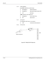
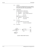
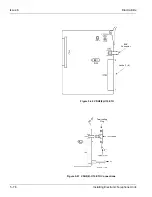
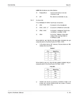
The OPX(2)-U10 ETU has one connector:
CN1
Connects to the backboard
5.6.5
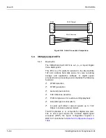
Connections
Figure 5-41 OPX(2)-U10 CN1 Connection
T1
R1
T2
R2
Single Line
Telephone
MDF
RJ-11
YL O RD O
BK O GR O
Summary of Contents for Electra Elite 192
Page 2: ...SYSTEM HARDWARE MANUAL Stock Number 750363 Issue 6 Series 6000 192 ...
Page 3: ......
Page 5: ......
Page 9: ...THIS PAGE INTENTIONALLY LEFT BLANK ...
Page 10: ...Regulatory Information ...
Page 11: ......
Page 20: ......
Page 52: ...Issue 6 Electra Elite xxxii List of Tables THIS PAGE INTENTIONALLY LEFT BLANK ...
Page 73: ...Electra Elite Issue 6 System Hardware Manual 1 21 THIS PAGE INTENTIONALLY LEFT BLANK ...
Page 74: ...Issue 6 Electra Elite 1 22 Introduction ...
Page 96: ...Issue 6 Electra Elite 2 22 System Specifications ...
Page 104: ...Issue 6 Electra Elite 3 8 Hardware Requirements THIS PAGE INTENTIONALLY LEFT BLANK ...
Page 213: ...Electra Elite Issue 6 System Hardware Manual 5 67 Figure 5 39 FMS 8 U10 ETU ...
Page 336: ...Issue 6 Electra Elite 7 54 Installing Optional Equipment THIS PAGE INTENTIONALLY LEFT BLANK ...
Page 368: ...Issue 6 Electra Elite A 4 Glossary of Abbreviations THIS PAGE INTENTIONALLY LEFT BLANK ...
Page 369: ...SYSTEM HARDWARE MANUAL NEC America Inc Issue 6 Series 6000 192 ...


