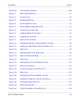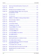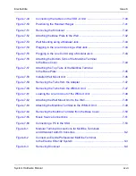
System Hardware Manual
xxix
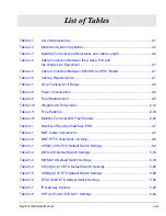
List of Tables
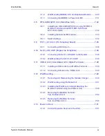
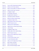
Table 2-1
List of Abbreviations ........................................................................................ 2-1
Table 2-2
Maximum System Capacities .......................................................................... 2-4
Table 2-3
Multiline Terminal Loop Resistance and Cable Length ................................... 2-6
Table 2-4
Cable Connection Between the Analog Port and
the Single Line Equipment .............................................................................. 2-7
Table 2-5
Cable Connection Between ESI/VDH and PCT Board ................................... 2-7
Table 2-6
Cabling Requirements ..................................................................................... 2-7
Table 2-7
Zone Transceiver II Range .............................................................................. 2-8
Table 2-8
Power Consumption ........................................................................................ 2-9
Table 2-9
Fuse Replacement .......................................................................................... 2-9
Table 2-10
Weights and Dimensions .............................................................................. 2-14
Table 2-11
Tone Patterns ................................................................................................ 2-19
Table 2-12
Multiline Terminal LED Flash Pattern ............................................................ 2-20
Table 3-1
Number of Required Interface ETUs ............................................................... 3-7
Table 4-1
MDF Cable Connections ................................................................................. 4-5
Table 4-2
MDF PFT Connections (J3 Only) .................................................................... 4-8
Table 5-1
CPUB( )-U10 ETU Default Switch Settings ..................................................... 5-9
Table 5-2
MIFA-U10 Default Switch Settings ................................................................ 5-16
Table 5-3
MIFM-U10 Default Switch Settings ............................................................... 5-19
Table 5-4
COI(4)/(8)-U10 ETU Default Switch Settings ................................................ 5-26
Table 5-5
COIB(4)-U10 ETU Default Switch Settings ................................................... 5-29
Table 5-6
DTI-U10/20 ETU Default Switch Settings ..................................................... 5-36
Table 5-7
IP Gateway Options ...................................................................................... 5-40
Table 5-8
PRT(1)-U10/20 ETU SW1 Settings ............................................................... 5-44
Summary of Contents for Electra Elite 192
Page 2: ...SYSTEM HARDWARE MANUAL Stock Number 750363 Issue 6 Series 6000 192 ...
Page 3: ......
Page 5: ......
Page 9: ...THIS PAGE INTENTIONALLY LEFT BLANK ...
Page 10: ...Regulatory Information ...
Page 11: ......
Page 20: ......
Page 52: ...Issue 6 Electra Elite xxxii List of Tables THIS PAGE INTENTIONALLY LEFT BLANK ...
Page 73: ...Electra Elite Issue 6 System Hardware Manual 1 21 THIS PAGE INTENTIONALLY LEFT BLANK ...
Page 74: ...Issue 6 Electra Elite 1 22 Introduction ...
Page 96: ...Issue 6 Electra Elite 2 22 System Specifications ...
Page 104: ...Issue 6 Electra Elite 3 8 Hardware Requirements THIS PAGE INTENTIONALLY LEFT BLANK ...
Page 213: ...Electra Elite Issue 6 System Hardware Manual 5 67 Figure 5 39 FMS 8 U10 ETU ...
Page 336: ...Issue 6 Electra Elite 7 54 Installing Optional Equipment THIS PAGE INTENTIONALLY LEFT BLANK ...
Page 368: ...Issue 6 Electra Elite A 4 Glossary of Abbreviations THIS PAGE INTENTIONALLY LEFT BLANK ...
Page 369: ...SYSTEM HARDWARE MANUAL NEC America Inc Issue 6 Series 6000 192 ...

