Electra Elite
Issue 6
System Hardware Manual
5 - 99
6.3.4
Connectors
Refer to
Table 5-30 Connector Descriptions (CN2)
and
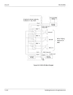
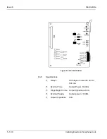
Figure 5-56 ECR-U10 ETU
.
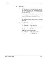
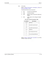
The ECR-U10 ETU has four connectors:
CN1
Connects to the Backboard
CN2
Contacts for Relays
CN3
Both-way Audio Connection for External
Paging
CN4
Audio output for Tone Ringer and Night
Chime
Refer to
Table 4-1 MDF Cable Connections
for all other
ECR-U10 cable connections.
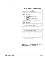
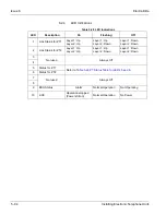
Table 5-30 Connector Descriptions (CN2)
Pin Number
Description
13~16
Not Used
12
General Purpose Relay #1
11
10
General Purpose Relay #0
9
5~8
Not Used
4
Zone Paging Audio Input
3
2
External Paging BGM input
1
Summary of Contents for Electra Elite 192
Page 2: ...SYSTEM HARDWARE MANUAL Stock Number 750363 Issue 6 Series 6000 192 ...
Page 3: ......
Page 5: ......
Page 9: ...THIS PAGE INTENTIONALLY LEFT BLANK ...
Page 10: ...Regulatory Information ...
Page 11: ......
Page 20: ......
Page 52: ...Issue 6 Electra Elite xxxii List of Tables THIS PAGE INTENTIONALLY LEFT BLANK ...
Page 73: ...Electra Elite Issue 6 System Hardware Manual 1 21 THIS PAGE INTENTIONALLY LEFT BLANK ...
Page 74: ...Issue 6 Electra Elite 1 22 Introduction ...
Page 96: ...Issue 6 Electra Elite 2 22 System Specifications ...
Page 104: ...Issue 6 Electra Elite 3 8 Hardware Requirements THIS PAGE INTENTIONALLY LEFT BLANK ...
Page 213: ...Electra Elite Issue 6 System Hardware Manual 5 67 Figure 5 39 FMS 8 U10 ETU ...
Page 336: ...Issue 6 Electra Elite 7 54 Installing Optional Equipment THIS PAGE INTENTIONALLY LEFT BLANK ...
Page 368: ...Issue 6 Electra Elite A 4 Glossary of Abbreviations THIS PAGE INTENTIONALLY LEFT BLANK ...
Page 369: ...SYSTEM HARDWARE MANUAL NEC America Inc Issue 6 Series 6000 192 ...

