


ANNEX 3. LASER DEVICE
C8
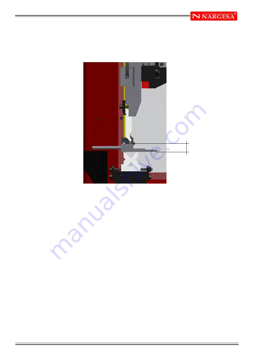
35 mm
12. Test 3. High speed stop
Placing the tooling on the die and with the thickness of 35mm on the interference área of the laser, we actí-
vate the stop of the ram on high speed mode and it has to stop before reaching the tooling. (Picture 8)
Picture 8
Once all these tests have been made, we finish the assembling operation of the units Emitter– Receptor on
the press brake.
Summary of Contents for MP3003 CNC
Page 2: ...Thank you for choosing our machines www nargesa com...
Page 18: ...Annex 1 Software ESA S630...
Page 19: ......
Page 68: ...Annex 2 Technical data...
Page 69: ......
Page 71: ...ANEX 2 TECHNICAL DATA MP3003CNC B3 1 List of parts...
Page 72: ...ANEX 2 TECHNICAL DATA MP3003CNC B4...
Page 73: ...ANEX 2 TECHNICAL DATA MP3003CNC B5...
Page 74: ...ANEX 2 TECHNICAL DATA MP3003CNC B6...
Page 75: ...ANEX 2 TECHNICAL DATA MP3003CNC B7...
Page 76: ...ANEX 2 TECHNICAL DATA MP3003CNC B8...
Page 77: ...ANEX 2 TECHNICAL DATA MP3003CNC B9...
Page 78: ...ANEX 2 TECHNICAL DATA MP3003CNC B10...
Page 79: ...ANEX 2 TECHNICAL DATA MP3003CNC B11...
Page 80: ...ANEX 2 TECHNICAL DATA MP3003CNC B12 2 Hydraulic group...
Page 81: ...ANEX 2 TECHNICAL DATA MP3003CNC B13...
Page 82: ...ANEX 2 TECHNICAL DATA MP3003CNC B14...
Page 83: ...ANEX 2 TECHNICAL DATA MP3003CNC B15 3 Upper cylinder...
Page 84: ...ANEX 2 TECHNICAL DATA MP3003CNC B16...
Page 85: ...ANEX 2 TECHNICAL DATA MP3003CNC B17 4 Main cylinder...
Page 86: ...ANEX 2 TECHNICAL DATA MP3003CNC B18...
Page 87: ...ANEX 2 TECHNICAL DATA MP3003CNC B19 5 Electric box...
Page 88: ...ANEX 2 TECHNICAL DATA MP3003CNC B20 6 Control panel box...
Page 89: ...ANEX 2 TECHNICAL DATA MP3003CNC B21 7 Electric maps...
Page 90: ...ANEX 2 TECHNICAL DATA MP3003CNC B22...
Page 91: ...ANEX 2 TECHNICAL DATA MP3003CNC B23...
Page 92: ...ANEX 2 TECHNICAL DATA MP3003CNC B24...
Page 93: ...ANEX 2 TECHNICAL DATA MP3003CNC B25...
Page 94: ...ANEX 2 TECHNICAL DATA MP3003CNC B26...
Page 95: ...ANEX 2 TECHNICAL DATA MP3003CNC B27...
Page 96: ......
Page 98: ...Annex 3 Laser devices...
Page 99: ......
Page 109: ...ANNEX 3 LASER DEVICE C11 15 List of parts right laser...
Page 110: ...ANNEX 3 LASER DEVICE C12...
Page 111: ...ANNEX 3 LASER DEVICE C13...