


NOTE: This data sheet has a new look — the technical content has not changed.
MOTOROLA CMOS LOGIC DATA
CHAPTER 7
7–5
OPTIMIZING THE LONG TERM RELIABILITY OF
PLASTIC PACKAGES
Todays plastic integrated circuit packages are as reliable
as ceramic packages under most environmental conditions.
However when the ultimate in system reliability is required,
thermal management must be considered as a prime system
design goal.
Modern plastic package assembly technology utilizes gold
wire bonded to aluminum bonding pads throughout the elec-
tronics industry. When exposed to high temperatures for pro-
tracted periods of time an intermetallic compound can form in
the bond area resulting in high impedance contacts and deg-
radation of device performance. Since the formation of inter-
metallic compounds is directly related to device junction
temperature, it is incumbent on the designer to determine
that the device junction temperatures are consistent with
system reliability goals.
Predicting Bond Failure Time:
Based on the results of almost ten (10) years of +125
_
C
operating life testing, a special arrhenius equation has been
developed to show the relationship between junction temper-
ature and reliability.
11554.267
Eq. (1) T = (6.376 x 10⁹)e
273.15 + TJ
Where: T = Time in hours to 0.1% bond failure (1 failure
Where: T =
per 1,000 bonds).
TJ = Device junction temperature,
_
C.
And:
Eq. (2) TJ = TA + PD
θ
JA = TA +
∆
TJ
Where: TJ = Device junction temperature,
_
C.
TA = Ambient temperature,
_
C.
PD = Device power dissipation in watts.
θ
JA = Device thermal resistance, junction to air,
_
C/Watt.
∆
TJ = Increase in junction temperature due to
on–chip power dissipation.
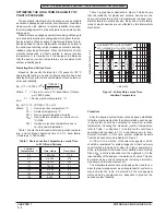
Table 1 shows the relationship between junction tempera-
ture, and continuous operating time to 0.1%. bond failure,
(1 failure per 1,000 bonds).
Table 1. Device Junction Temperature versus Time
to 0.1% Bond Failures
ÎÎÎÎÎÎ
ÎÎÎÎÎÎ
Junction
Temperature
_
C
ÎÎÎÎÎÎ
ÎÎÎÎÎÎ
Time, Hours
ÎÎÎÎÎÎ
ÎÎÎÎÎÎ
Time, Years
ÎÎÎÎÎÎ
ÎÎÎÎÎÎ
80
ÎÎÎÎÎÎ
ÎÎÎÎÎÎ
1,032,200
ÎÎÎÎÎÎ
ÎÎÎÎÎÎ
117.8
ÎÎÎÎÎÎ
ÎÎÎÎÎÎ
90
ÎÎÎÎÎÎ
ÎÎÎÎÎÎ
419,300
ÎÎÎÎÎÎ
ÎÎÎÎÎÎ
47.9
ÎÎÎÎÎÎ
ÎÎÎÎÎÎ
100
ÎÎÎÎÎÎ
ÎÎÎÎÎÎ
178,700
ÎÎÎÎÎÎ
ÎÎÎÎÎÎ
20.4
ÎÎÎÎÎÎ
ÎÎÎÎÎÎ
110
ÎÎÎÎÎÎ
ÎÎÎÎÎÎ
79,600
ÎÎÎÎÎÎ
ÎÎÎÎÎÎ
9.4
ÎÎÎÎÎÎ
ÎÎÎÎÎÎ
120
ÎÎÎÎÎÎ
ÎÎÎÎÎÎ
37,000
ÎÎÎÎÎÎ
ÎÎÎÎÎÎ
4.2
ÎÎÎÎÎÎ
ÎÎÎÎÎÎ
130
ÎÎÎÎÎÎ
ÎÎÎÎÎÎ
17,800
ÎÎÎÎÎÎ
ÎÎÎÎÎÎ
2.0
ÎÎÎÎÎÎ
140
ÎÎÎÎÎÎ
8,900
ÎÎÎÎÎÎ
1.0
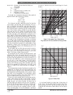
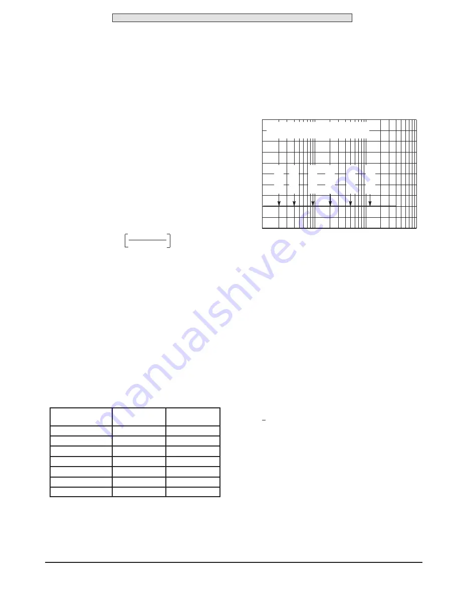
Table 1 is graphically illustrated in Figure 7 which shows
that the reliability for plastic and ceramic devices are the
same until elevated junction temperatures induces inter-
metallic failures in plastic devices. Early and mid–life failure
rates of plastic devices are not effected by this intermetallic
mechanism.
Figure 7. Failure Rate versus Time
Junction Temperature
1000
100
10
1
TIME, YEARS
NORMALIZED F
AILURE RA
TE
1
FAILURE RATE OF PLASTIC = CERAMIC
UNTIL INTERMETALLIC FAILURES OCCUR
T
J
= 120
C
°
T
J
= 130
C
°
T
J
= 1
10
C
°
T
J
= 100
C
°
T
J
= 90
C
°
T
J
= 80
C
°
Procedure
After the desired system failure rate has been established
for failure mechanisms other than intermetallics, each device
in the system should be evaluated for maximum junction
temperature. Knowing the maximum junction temperature,
refer to Table 1 or Equation 1 to determine the continuous
operating time required to 0.1% bond failures due to inter-
metallic formation. At this time, system reliability departs
from the desired value as indicated in Figure 7.
Air flow is one method of thermal management which
should be considered for system longevity. Other commonly
used methods include heat sinks for higher powered de-
vices, refrigerated air flow and lower density board stuffing.
Since
θ
CA is entirely dependent on the application, it is the
responsibility of the designer to determine its value. This can
be achieved by various techniques including simulation,
modeling, actual measurement, etc.
The material presented here emphasizes the need to con-
sider thermal management as an integral part of system de-
sign and also the tools to determine if the management
methods being considered are adequate to produce the
desired system reliability.
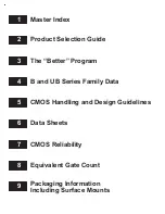
Summary of Contents for CMOS Logic
Page 1: ......
Page 5: ...iv MOTOROLA CMOS LOGIC DATA ...
Page 6: ...Master Index 1 ...
Page 12: ...Product Selection Guide 2 ...
Page 17: ...The Better Program 3 ...
Page 20: ...B and UB Series Family Data 4 ...
Page 25: ...CMOS Handling and Design Guidelines 5 ...
Page 32: ...CMOS Handling and Design Guidelines 5 ...
Page 39: ...Data Sheets 6 ...
Page 234: ...MOTOROLA CMOS LOGIC DATA MC14174B 6 196 FUNCTIONAL BLOCK DIAGRAM TIMING DIAGRAM ...
Page 238: ...MOTOROLA CMOS LOGIC DATA MC14175B 6 200 FUNCTIONAL BLOCK DIAGRAM TIMING DIAGRAM ...
Page 555: ...CMOS Reliability 7 ...
Page 561: ...Equivalent Gate Count 8 ...
Page 563: ...Packaging Information Including Surface Mounts 9 ...
Page 571: ......