


MOTOROLA CMOS LOGIC DATA
6–511
MC14597B MC14598B
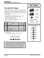
8-Bit Bus-Compatible Latches
The MC14597B and MC14598B are 8–bit latches, one addressed with an
internal counter and the other addressed with an external binary address.
The 8 latch–outputs are high drive, three–state and bus line compatible. The
drive capability allows direct applications with MPU systems such as the
Motorola 6800 family.
With MC14597B, a 3–bit address counter (clocked on the falling edge of
Increment) selects the appropriate latch. The latches of the MC14598B are
accessed via the Address pins, A0, A1, and A2. A Full Flag is provided on
the MC14597B to indicate the position of the Address counter.
All 8 outputs from the latches are available in parallel when Enable is in the
low state. Data is entered into a selected latch from the Data pin when the
Strobe is high. Master reset is available on both parts.
•
Serial Data Input
•
Three–State Bus Compatible Parallel Outputs
•
Three–State Control Pin (Enable) TTL Compatible Input
•
Open Drain Full Flag (Multiple Latch Wire–O Ring)
•
Master Reset
•
Level Shifting Inputs on All Except Enable
•
Diode Protection — All Inputs
•
Supply Voltage Range — 3.0 Vdc to 18 Vdc
•
Capable of Driving TTL Over Rated Temperature Range
With Fanout as Follows:
1 TTL Load
4 LSTTL Loads
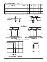
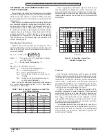
BLOCK DIAGRAMS
MC14598B
MC14597B
Enable
Outputs
1
High Impedance
0
Dn
Dn = State of nth latch
OUTPUT
TRUTH TABLE
13
14
15
16
9
10
11
12
5
4
3
2
1
8
7
6
D4
D3
D2
D1
VDD
D7
D6
D5
ENABLE
DATA
RESET
D0
VSS
INCREMENT
STROBE
FULL
NC
DATA
RESET
D0
VSS
A1
A0
STROBE
ENABLE
D3
D2
D1
VDD
A2
D7
D6
D5
D4
14
15
16
17
18
10
11
12
13
5
4
3
2
1
9
8
7
6
NC = NO CONNECTION
THREE
STATE
OUTPUT
BUFFERS
8
LATCHES
ADDRESS
DECODER
3–BIT
ADDRESS
COUNTER
FULL
LOGIC
RESET
LOGIC
RESET
2
4
ENABLE
1
15
14
13
12
11
10
9
D0
D1
D2
D3
D4
D5
D6
D7
DATA
3
STROBE
6
INCREMENT
5
FULL
VDD = 16
VSS = 8
7
1
17
16
15
14
13
12
11
D0
D1
D2
D3
D4
D5
D6
D7
ENABLE
4
THREE
STATE
OUTPUT
BUFFERS
8
LATCHES
ADDRESS
DECODER
VDD = 18
VSS = 9
2
3
6
RESET
DATA
STROBE
A0
A1
A2
7
8
10
MOTOROLA
SEMICONDUCTOR TECHNICAL DATA
MC14597B
MC14598B
L SUFFIX
CERAMIC
CASE 620
ORDERING INFORMATION
MC14597BCP
Plastic
MC14597BCL
Ceramic
MC14597BDW
SOIC
TA = – 55
°
to 125
°
C for all packages.
P SUFFIX
PLASTIC
CASE 648
D SUFFIX
SOIC
CASE 751B
L SUFFIX
CERAMIC
CASE 726
P SUFFIX
PLASTIC
CASE 707
ORDERING INFORMATION
MC14598BCP
Plastic
MC14598BCL
Ceramic
TA = – 55
°
to 125
°
C for all packages.
Summary of Contents for CMOS Logic
Page 1: ......
Page 5: ...iv MOTOROLA CMOS LOGIC DATA ...
Page 6: ...Master Index 1 ...
Page 12: ...Product Selection Guide 2 ...
Page 17: ...The Better Program 3 ...
Page 20: ...B and UB Series Family Data 4 ...
Page 25: ...CMOS Handling and Design Guidelines 5 ...
Page 32: ...CMOS Handling and Design Guidelines 5 ...
Page 39: ...Data Sheets 6 ...
Page 234: ...MOTOROLA CMOS LOGIC DATA MC14174B 6 196 FUNCTIONAL BLOCK DIAGRAM TIMING DIAGRAM ...
Page 238: ...MOTOROLA CMOS LOGIC DATA MC14175B 6 200 FUNCTIONAL BLOCK DIAGRAM TIMING DIAGRAM ...
Page 555: ...CMOS Reliability 7 ...
Page 561: ...Equivalent Gate Count 8 ...
Page 563: ...Packaging Information Including Surface Mounts 9 ...
Page 571: ......