


MOTOROLA CMOS LOGIC DATA
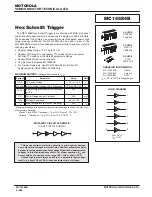
MC14597B MC14598B
6–516
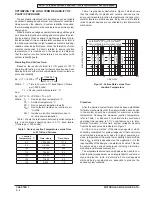
TRUTH TABLE FOR MC14597B
Address
Increment
Enable
Reset
Counter
Full
X
1
Count Up
—
X
1
No Change
—
X
1
0
Reset to Zero
Set to One
X
0
1
No Change
Set to One
If at
To Zero on
X
1
1
ADDRESS 7
Falling Edge
of STROBE
X = Don’t care
LATCH TRUTH TABLE
Address
Other
Strobe
Reset
Latch
Latches
0
1
*
*
1
1
Data
*
X
0
0
0
* = No change in state of latch
X = Don’t care
TEST LOAD
ALL OUTPUTS
Dn
+5.0 V
RL = 2.5 k
11.7 k
130 pF
Circuit diagrams external to or containing Motorola prod-
ucts are included as a means of illustration only. Complete
information sufficient for construction purposes may not be
fully illustrated. Although the information herein has been
carefully checked and is believed to be reliable. Motorola
assumes no responsibility for inaccuracies. Information here-
in does not convey to the purchaser any license under the
patent rights of Motorola or others.
The information contained herein is for guidance only, with
no warranty of any type, expressed or implied. Motorola re-
serves the right to make any changes to the information and
the product(s) to which the information applies and to discon-
tinue manufacture of the product(s) at any time.
Summary of Contents for CMOS Logic
Page 1: ......
Page 5: ...iv MOTOROLA CMOS LOGIC DATA ...
Page 6: ...Master Index 1 ...
Page 12: ...Product Selection Guide 2 ...
Page 17: ...The Better Program 3 ...
Page 20: ...B and UB Series Family Data 4 ...
Page 25: ...CMOS Handling and Design Guidelines 5 ...
Page 32: ...CMOS Handling and Design Guidelines 5 ...
Page 39: ...Data Sheets 6 ...
Page 234: ...MOTOROLA CMOS LOGIC DATA MC14174B 6 196 FUNCTIONAL BLOCK DIAGRAM TIMING DIAGRAM ...
Page 238: ...MOTOROLA CMOS LOGIC DATA MC14175B 6 200 FUNCTIONAL BLOCK DIAGRAM TIMING DIAGRAM ...
Page 555: ...CMOS Reliability 7 ...
Page 561: ...Equivalent Gate Count 8 ...
Page 563: ...Packaging Information Including Surface Mounts 9 ...
Page 571: ......