


MOTOROLA CMOS LOGIC DATA
6–285
MC14516B
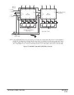
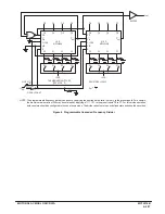
Figure 3. Presettable Cascaded 8–Bit Up/Down Counter
NOTE: The Least Significant Digit (L.S.D.) counts from a preset value once Preset Enable (PE) goes low. The Most Significant
Digit (M.S.D.) is disabled while Cin is high. When the count of the L.S.D. reaches 0 (count down mode) or reaches 15 (count
up mode), Cout goes low for one complete clock cycle, thus allowing the next counter to decrement/increment one count.
(See Timing Diagram) The L.S.D. now counts through another cycle (15 clock pulses) and the above cycle is repeated.
L.S.D.
MC14516B
Cout
Q0
Q1
Q2
Q3
P0
P1
P2
P3
PE
R
U/D
CLOCK
Cin
M.S.D.
MC14516B
Cout
Q0
Q1
Q2
Q3
P0
P1
P2
P3
PE
R
U/D
CLOCK
Cin
Q0
Q1
Q2
Q3
Q4
Q5
Q6
Q7
TERMINAL COUNT
INDICATOR
P0
P1
P2
P3
P4
P5
P6
P7
THUMBWHEEL SWITCHES
(OPEN FOR “0”)
+VDD
+VDD
+VDD
OPEN = COUNT
CLOCK
RESET
RESISTORS = 10 k
W
0 = COUNT
1 = PRESET
1 = UP
0 = DOWN
PRESET
ENABLE
Summary of Contents for CMOS Logic
Page 1: ......
Page 5: ...iv MOTOROLA CMOS LOGIC DATA ...
Page 6: ...Master Index 1 ...
Page 12: ...Product Selection Guide 2 ...
Page 17: ...The Better Program 3 ...
Page 20: ...B and UB Series Family Data 4 ...
Page 25: ...CMOS Handling and Design Guidelines 5 ...
Page 32: ...CMOS Handling and Design Guidelines 5 ...
Page 39: ...Data Sheets 6 ...
Page 234: ...MOTOROLA CMOS LOGIC DATA MC14174B 6 196 FUNCTIONAL BLOCK DIAGRAM TIMING DIAGRAM ...
Page 238: ...MOTOROLA CMOS LOGIC DATA MC14175B 6 200 FUNCTIONAL BLOCK DIAGRAM TIMING DIAGRAM ...
Page 555: ...CMOS Reliability 7 ...
Page 561: ...Equivalent Gate Count 8 ...
Page 563: ...Packaging Information Including Surface Mounts 9 ...
Page 571: ......