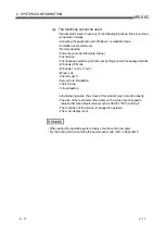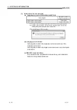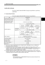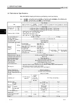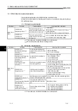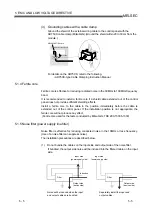
5 - 3 5 - 3
MELSEC
5 EMC AND LOW VOLTAGE DIRECTIVE
5.1.2 Installation in a control panel
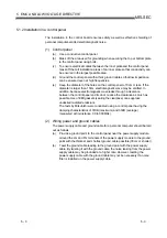
The installation in the control board ensures safety as well as effective shielding of
personal computer-emitted electromagnetic noise.
(1) Control panel
(a) Use a conductive control panel.
(b) Mask off the area used for grounding when securing the top or bottom plate
to the control panel using bolts.
(c) To ensure electrical contact between the inner plate and the control panel,
mask off the bolt installation areas of an inner plate so that conductivity can
be ensured in the largest possible area.
(d) Ground the control panel with a thick ground cable so that low impedance
can be ensured even at high frequencies.
(e) Keep the diameter of the holes on the control panel to 10cm or less. If the
diameter is larger than 10cm, electromagnetic wave may be emitted. In
addition, because electromagnetic wave leaks through a clearance
between the control panel and its door, reduce the clearance as much as
possible. Use of EMI gaskets (sealing the clearance) can suppress
undesired radiated emissions.
The tests by Mitsubishi were conducted using a control panel having the
damping characteristics of 37dB (maximum) and 30dB (average)
(measured at 3m distance, 30 to 300MHz).
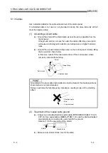
(2) Wiring power and ground cables
The power supply cable and ground cable for a personal computer should be laid
out as follows:
(a) Provide a ground point to the control panel near the power supply module.
Ground the LG and FG terminals of the power supply module to the ground
point with the thickest and shortest ground cable possible (30cm or shorter).
(b) Twist the ground cable leading to the ground point with the power supply
cable. By twisting it with the ground cable, the noise leaking from the power
supply cable may be grounded at a higher rate. However, twisting the
power supply cable with the ground cable may not be necessary if a noise
filter is installed on the power supply cable.
Summary of Contents for Q80BD-J71BR11
Page 2: ......
Page 24: ...A 22 A 22 MEMO ...
Page 50: ...4 6 4 6 MELSEC 4 FUNCTION MEMO ...
Page 92: ...6 36 6 36 MELSEC 6 PROCEDURE AND SETTINGS UP TO THE POINT OF OPERATION MEMO ...
Page 132: ...10 2 10 2 MELSEC 10 MELSEC DATA LINK LIBRARY MEMO 10 ...
Page 138: ...11 6 11 6 MELSEC 11 PROGRAMMING MEMO ...
Page 164: ...12 26 12 26 MELSEC 12 APPLICATION FUNCTIONS MEMO ...
Page 166: ...13 2 13 2 MELSEC 13 ERROR CODE MEMO 13 ...
Page 223: ......

