A - 13 A - 13
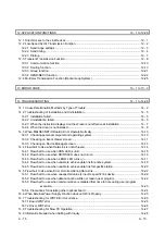
4 FUNCTION
4- 1 to 4- 6
4.1 Function List ............................................................................................................................................ 4- 1
4.2 Specifications of the Link Data Sending/Receiving Processing Time ................................................... 4- 2
4.2.1 Link data sending/receiving processing .......................................................................................... 4- 2
4.3 Driver WDT function ................................................................................................................................ 4- 5
5 EMC AND LOW VOLTAGE DIRECTIVE
5- 1 to 5- 6
5.1 Measures to comply with the EMC Directive ......................................................................................... 5- 1
5.1.1 EMC Directive related standards ..................................................................................................... 5- 2
5.1.2 Installation in a control panel ........................................................................................................... 5- 3
5.1.3 Cables ............................................................................................................................................. 5- 4
5.1.4 Ferrite core ....................................................................................................................................... 5- 5
5.1.5 Noise filter (power supply line filter) ................................................................................................. 5- 5
5.2 Requirements for Conformance to Low Voltage Directive .................................................................... 5- 6
6 PROCEDURE AND SETTINGS UP TO THE POINT OF OPERATION
6- 1 to 6-36
6.1 Procedure Up to the Point of Operation ................................................................................................. 6- 1
6.2 Part Names and Settings ........................................................................................................................ 6- 2
6.3 Installation ............................................................................................................................................... 6- 7
6.3.1 Handling precautions ....................................................................................................................... 6- 7
6.3.2 Installation environment ................................................................................................................... 6- 7
6.3.3 Board installation .............................................................................................................................. 6- 8
6.3.4 Channel No. settings ........................................................................................................................ 6- 9
6.4 Wiring ...................................................................................................................................................... 6-10
6.4.1 Optical loop system .......................................................................................................................... 6-12
6.4.2 Coaxial bus system .......................................................................................................................... 6-14
6.4.3 Connecting the connector for the coaxial cable .............................................................................. 6-19
6.4.4 External power supply cable wiring ................................................................................................. 6-23
6.5 Test .......................................................................................................................................................... 6-25
6.5.1 Self-loopback test ............................................................................................................................. 6-26
6.5.2 Internal self-loopback test ................................................................................................................ 6-28
6.5.3 H/W test ............................................................................................................................................ 6-30
6.5.4 Station to station test ........................................................................................................................ 6-31
6.5.5 Forward loop/Reverse loop test ....................................................................................................... 6-34
7 PARAMETER SETTINGS
7- 1 to 7-12
7.1 Board Information Settings ..................................................................................................................... 7- 2
7.2 Network Settings ..................................................................................................................................... 7- 3
7.2.1 Network No. ...................................................................................................................................... 7- 3
7.2.2 Station No. ........................................................................................................................................ 7- 3
7.2.3 Control station/Normal station ......................................................................................................... 7- 3
7.2.4 Group No. ......................................................................................................................................... 7- 4
7.2.5 Mode setting ..................................................................................................................................... 7- 4
7.2.6 Parameter setting example .............................................................................................................. 7- 5
Summary of Contents for Q80BD-J71BR11
Page 2: ......
Page 24: ...A 22 A 22 MEMO ...
Page 50: ...4 6 4 6 MELSEC 4 FUNCTION MEMO ...
Page 92: ...6 36 6 36 MELSEC 6 PROCEDURE AND SETTINGS UP TO THE POINT OF OPERATION MEMO ...
Page 132: ...10 2 10 2 MELSEC 10 MELSEC DATA LINK LIBRARY MEMO 10 ...
Page 138: ...11 6 11 6 MELSEC 11 PROGRAMMING MEMO ...
Page 164: ...12 26 12 26 MELSEC 12 APPLICATION FUNCTIONS MEMO ...
Page 166: ...13 2 13 2 MELSEC 13 ERROR CODE MEMO 13 ...
Page 223: ......


