6 - 16 6 - 16
MELSEC
6 PROCEDURE AND SETTINGS UP TO THE POINT OF OPERATION
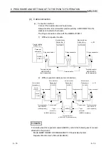
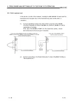
(2) Cable connection
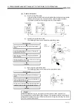
(a) Connection method
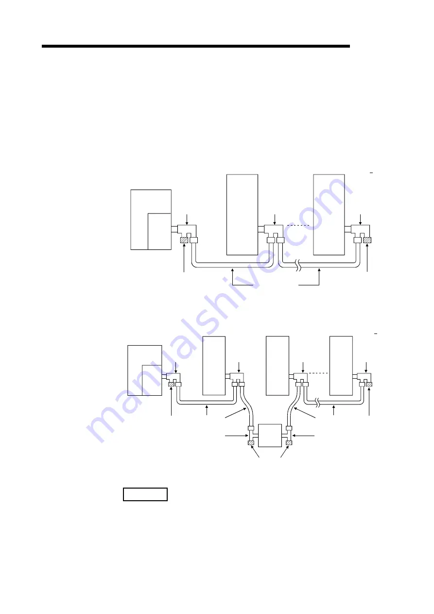
Connect the coaxial cable as shown below.
Always install a terminal resistor (sold separately: A6RCON-R75) to the
stations connected at both ends.
The F-type connector comes with the Q80BD-J71BR11.
1) Without a repeater module
Personal
computer
QJ71BR11
QJ71BR11
Control station
Station No. 1
Normal station
Station No. n
Normal station
Station No. 2
F-type connector
Coaxial cable
Terminal resistor
A6RCON-R75
(sold separately)
F-type connector
F-type connector
Terminal resistor
A6RCON-R75
(sold separately)
n
≤
32
Q80BD-
J71BR11
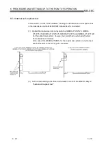
2) With a repeater module (series connection)
A6BR10
Personal
computer
Control station
Station No. 1
QJ71BR11
Normal station
Station No. 2
QJ71BR11
Normal station
Station No. 3
QJ71BR11
Normal station
Station No. n
F-type connector
Coaxial cable
T-type
connector
(A6BR10 accessory)
T-type
connector
(A6BR10 accessory)
Coaxial cable
Terminal resistor
A6RCON-R75
(sold separately)
Terminal resistor
A6RCON-R75 (sold separately)
F-type connector
F-type connector
F-type connector
Terminal resistor
A6RCON-R75
(sold separately)
n
≤
32
Q80BD-
J71BR11
REMARK
For details about the repeater module (A6BR10), refer to the following user's manual
attached to the product:
Model A6BR10/A6BR10-DC MELSECNET/10 Coaxial Bus System
Repeater Module User's Manual (IB-66499)
Summary of Contents for Q80BD-J71BR11
Page 2: ......
Page 24: ...A 22 A 22 MEMO ...
Page 50: ...4 6 4 6 MELSEC 4 FUNCTION MEMO ...
Page 92: ...6 36 6 36 MELSEC 6 PROCEDURE AND SETTINGS UP TO THE POINT OF OPERATION MEMO ...
Page 132: ...10 2 10 2 MELSEC 10 MELSEC DATA LINK LIBRARY MEMO 10 ...
Page 138: ...11 6 11 6 MELSEC 11 PROGRAMMING MEMO ...
Page 164: ...12 26 12 26 MELSEC 12 APPLICATION FUNCTIONS MEMO ...
Page 166: ...13 2 13 2 MELSEC 13 ERROR CODE MEMO 13 ...
Page 223: ......

