


USER MANUAL, RSS-1000-CVSI
7000-5970
Rev.
A
page
163
of
396
4.4.10. Cancel
4.4.10.1. Aborts the parameter edit and prevents any changes from being made.
5. Once the desired values have been entered, tap the Save Button to save all changes.
6. Tap
to enter the desired Solder Wire Feeder settings
6.1. Details on the setting covered in
Feeding Solder
Section
7. Jog to the location of the first point of the Solder Line
8. Tap the Record button
8.1. A pink dot will appear on the screen to signify that a point has been recorded
9. Jog to the location of where the Solder line is to end.
9.1. Warning: Please note that the robot uses vector movements (i.e. will move in all three
directional Axes and rotation about the Z-Axis simultaneously.) Therefore, this factor should
be considered when programming the second point to create the line. For this reason, the
directional jog controls should be used rather than touching on the work space to jog to
prevent a change in height when producing a solder line.
10. Tap the Record button
to establish the 2
nd
point.
10.1.
As soon as the button is tapped, the software will create a line (in pink) from the first
point that was programmed in step 6 to the 2
nd
point that was programmed in step 8.
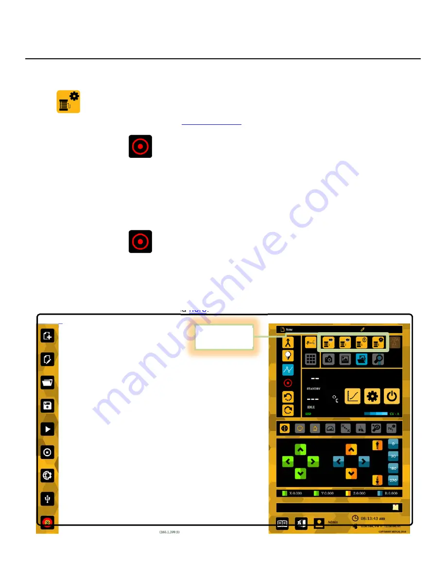
FEEDING
SOLDER
Solder can be fed one of two ways: Manual Feed and Programmable Feed. A description of each of
the Solder Feeder functions can be found
here
.
Solder Feeder
Options
Summary of Contents for RSS-1000-CVSI
Page 21: ...USER MANUAL RSS 1000 CVSI 7000 5970 Rev A page 21 of 396 ROBOT BASE CONNECTIONS N ...
Page 52: ...USER MANUAL RSS 1000 CVSI 7000 5970 Rev A page 52 of 396 2 Tap the Power Button ...
Page 55: ...USER MANUAL RSS 1000 CVSI 7000 5970 Rev A page 55 of 396 2 Tap the Power Button ...
Page 224: ...USER MANUAL RSS 1000 CVSI 7000 5970 Rev A page 224 of 396 5 5 Spiral 1 2 3 8 9 4 7 6 5 ...


