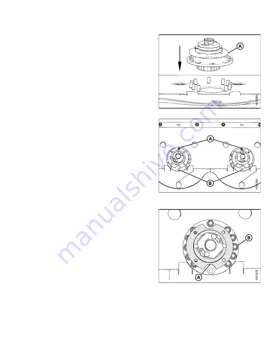
5. Insert spindle (A) into cutterbar.
Figure 4.58: Left-Hand Spindle
6. Insert studs (A) into spindle as shown.
NOTE:
Plugs are factory installed as shown in position
(B) but may come loose over time. Ensure studs
are inserted into proper location.
IMPORTANT:
Ensure clockwise spindles rotate clockwise
and counterclockwise spindles (with machined
grooves) rotate counterclockwise. The offset
gear design makes it possible to install spindles
having an opposite rotation of what is intended
which will prevent discs from spinning up after
impact resulting in cutterbar component damage.
Figure 4.59: Spindle Orientation
7. Rotate spindle hub (A) to access studs, and install 11
M12 lock nuts (B) and washers. Torque bolts to 37 ft
·
lbf
(50 N
·
m).
Figure 4.60: Left-Hand Spindle Hub
and Hardware
169820
151
Revision A


