MacDon R113, Operator'S Manual
Introducing Eldom R113 - a versatile and user-friendly appliance designed to enhance your daily routine. To ensure you get the most out of this exceptional device, a comprehensive User Manual is available for download absolutely free from manualshive.com. Explore its advanced features and unleash the full potential of Eldom R113 today!
Share
Download


Reviews:
No comments
Related manuals for R113

Prism
Brand: Labnet Pages: 12

MKHF
Brand: Vahle Pages: 36

KBH
Brand: Vahle Pages: 20

NXP series
Brand: Vacon Pages: 102

CS-5000 Series
Brand: Iwatsu Pages: 234

DURO-A RC
Brand: Rohm Pages: 91
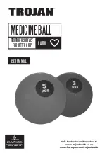
MEDICINE BALL
Brand: Trojan Pages: 12

100 Series Z Master
Brand: Toro Pages: 28

69787
Brand: SPARTAN sport Pages: 8

RIDA qLine Scan
Brand: R-Biopharm Pages: 24

ZOLAR Vega 30C
Brand: Z-CAM Pages: 45

AQUAvalve5 1Pot
Brand: Autopot Pages: 2

CleanFreak 1200-01
Brand: Medovations Pages: 3

FHH074
Brand: Graco Pages: 114

VQ1001
Brand: MEDISTIM Pages: 34

580083
Brand: OttLite Pages: 5
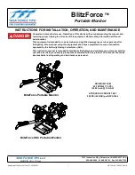
BlitzForce XXLC-33-NH1
Brand: Task Force Tips Pages: 16

15537
Brand: Walimex Pro Pages: 7


