SmartDGA Hardware Manual
Maintenance
•
86
7.3
Sensor Replacement
Note:
Each H
2
and O
2
sensor has its own calibration file that needs to be loaded after
sensor replacement; please contact LumaSense for further details prior to performing
sensor replacement.
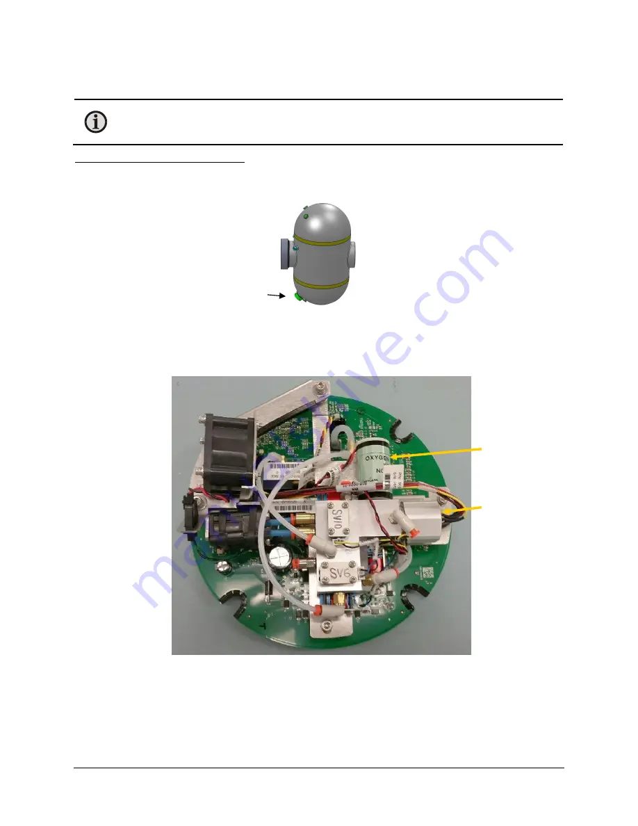
To gain access to the gas manifold:
1.
After powering down the EZHub, remove the the power/communications cable with multi-
pin connector from the bottom dome of the SmartDGA instrument.
2.
Remove the twelve screws using a 9/64” hex driver and carefully lift up the top dome to
remove it from the central housing.
The gas manifold will be the aluminum block attached to the top of the 8” printed circuit
board (PCB).
Gas Manifold
Multi-pin connector
Oxygen sensor
Hydrogen sensor
holding nut
Summary of Contents for SmartDGA
Page 1: ...HARDWARE MANUAL SmartDGA...
Page 99: ...SmartDGA Hardware Manual Diagrams Drawings 99 9 5 SmartDGA NEMA 4 Enclosure...
Page 100: ...SmartDGA Hardware Manual Diagrams Drawings 100 9 6 Inline Mounting Plate...
Page 102: ...SmartDGA Hardware Manual Diagrams Drawings 102 9 8 Assy Wall Mount SmartDGA EZHubTM...
Page 103: ...SmartDGA Hardware Manual Diagrams Drawings 103...
Page 104: ...SmartDGA Hardware Manual Diagrams Drawings 104 9 9 Assy Panel Mount SmartDGA EZHubTM...
Page 105: ...SmartDGA Hardware Manual Diagrams Drawings 105...
Page 106: ...SmartDGA Hardware Manual Diagrams Drawings 106 9 10 Assy Wall Mount LumaSMART iCoreTM...
Page 107: ...SmartDGA Hardware Manual Diagrams Drawings 107...
Page 108: ...SmartDGA Hardware Manual Diagrams Drawings 108 9 11 Assy Panel Mount LumaSMART iCoreTM...
Page 109: ...SmartDGA Hardware Manual Diagrams Drawings 109...
Page 110: ...SmartDGA Hardware Manual Diagrams Drawings 110 9 12 SmartDGA Instrument Sun Shade...
Page 111: ...SmartDGA Hardware Manual Diagrams Drawings 111...


