SmartDGA Hardware Manual
SmartDGA System Installation
•
65
To connect RS485 to the PC:
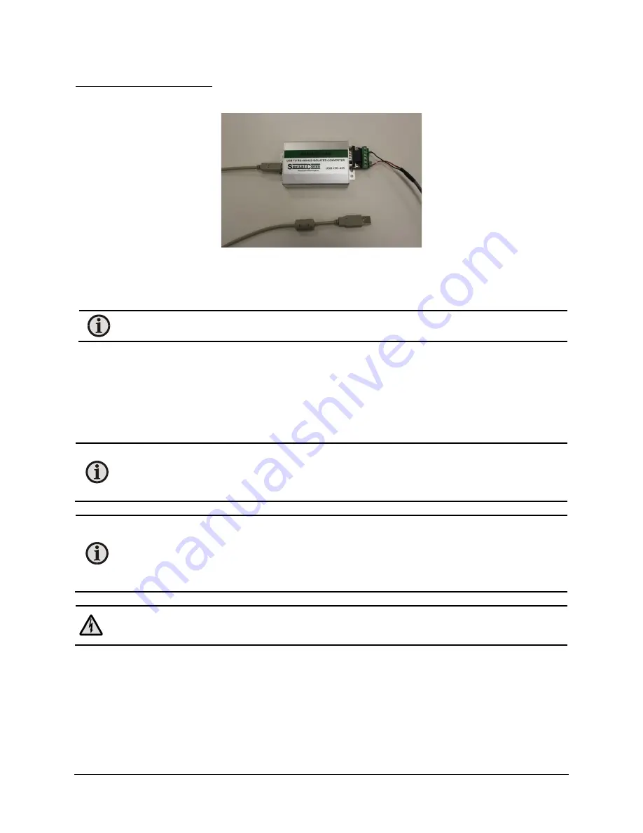
If using RS485 with a PC, you will need to connect the RS485-USB converter:
1.
Plug in 3-pin connector from the converter cable into the EZHub RS485 Out port.
2.
Plug in the 6-pin connector from the converter cable into the Converter Serial Comm Port.
3.
Plug the “square” USB side into the converter box and the standard USB side into your
computer USB port.
Note:
Power for the connector is drawn from the computer.
4.
Once powered, your computer may take a few minutes to identify and may install some
driver software. If your computer does not automatically install the software, use the
enclosed CD to install the software.
Power Supply Wiring
No power cord is supplied with the LumaSMART
i
Core unit. However, the connector and pins are
provided.
Note:
The
i
Core requires 90 to 264 Volts AC, 127 VDC to 370 VDC, 47-63 Hz,
2.5 A max. Use size 18 AWG wire for the included crimps and connectors to bring power
to the EZHub. We recommend a power cable with the following characteristics: 18 AWG
and UL 1061 (300V, 80C) approved.
Note:
Each
i
Core unit requires that there be a 10A circuit breaker (separate from any
other
i
Core or EZHub units) on the power line that feeds it as a secondary line. This circuit
breaker is used to power the unit ON and OFF. The LumaSMART
i
Core unit does not
include any external switches or circuit breakers. Consult local building codes for the
appropriate switch or circuit breaker to install. Externally fuse for 200W.
Warning:
Exercise proper electrical procedures when wiring the electrical input power
connectors to ensure complete insulation of electrical conductors.
1.
Route the
i
Core power cable from the circuit breaker to the
i
Core location.
2.
Once the cable has been routed, cut the cable to the appropriate length. The connection for
the AC/DC input is located at the bottom of the LumaSMART
i
Core unit.
Summary of Contents for SmartDGA
Page 1: ...HARDWARE MANUAL SmartDGA...
Page 99: ...SmartDGA Hardware Manual Diagrams Drawings 99 9 5 SmartDGA NEMA 4 Enclosure...
Page 100: ...SmartDGA Hardware Manual Diagrams Drawings 100 9 6 Inline Mounting Plate...
Page 102: ...SmartDGA Hardware Manual Diagrams Drawings 102 9 8 Assy Wall Mount SmartDGA EZHubTM...
Page 103: ...SmartDGA Hardware Manual Diagrams Drawings 103...
Page 104: ...SmartDGA Hardware Manual Diagrams Drawings 104 9 9 Assy Panel Mount SmartDGA EZHubTM...
Page 105: ...SmartDGA Hardware Manual Diagrams Drawings 105...
Page 106: ...SmartDGA Hardware Manual Diagrams Drawings 106 9 10 Assy Wall Mount LumaSMART iCoreTM...
Page 107: ...SmartDGA Hardware Manual Diagrams Drawings 107...
Page 108: ...SmartDGA Hardware Manual Diagrams Drawings 108 9 11 Assy Panel Mount LumaSMART iCoreTM...
Page 109: ...SmartDGA Hardware Manual Diagrams Drawings 109...
Page 110: ...SmartDGA Hardware Manual Diagrams Drawings 110 9 12 SmartDGA Instrument Sun Shade...
Page 111: ...SmartDGA Hardware Manual Diagrams Drawings 111...


