SmartDGA Hardware Manual
Maintenance
•
85
3.
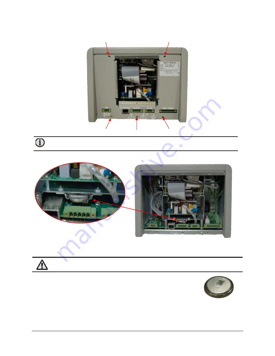
Removed the bottom “U-shaped” panel using a medium Phillips head screwdriver.
Save the (5) screws.
Note:
You may need to use a small Flat head screwdriver in order to remove this panel
if it is tight.
4.
Locate the battery directly above the 5-pin “SERIAL” connector.
5.
Remove the old battery by pushing down on the retention tab and then sliding the battery
straight out.
Caution:
Use rubber gloves or other protection when handling the new battery, as
finger prints can reduce the battery’s life span.
6.
Insert the new battery into the holder with the positive side facing
down (toward the “SERIAL” connector).
7.
Reattach the “U-shaped” and small access panels.
8.
Reconnect the iCore unit and bring the system back online.
9.
Using the touchscreen, navigate to the
Battery Life
software screen and press the
Reset
button.
Summary of Contents for SmartDGA
Page 1: ...HARDWARE MANUAL SmartDGA...
Page 99: ...SmartDGA Hardware Manual Diagrams Drawings 99 9 5 SmartDGA NEMA 4 Enclosure...
Page 100: ...SmartDGA Hardware Manual Diagrams Drawings 100 9 6 Inline Mounting Plate...
Page 102: ...SmartDGA Hardware Manual Diagrams Drawings 102 9 8 Assy Wall Mount SmartDGA EZHubTM...
Page 103: ...SmartDGA Hardware Manual Diagrams Drawings 103...
Page 104: ...SmartDGA Hardware Manual Diagrams Drawings 104 9 9 Assy Panel Mount SmartDGA EZHubTM...
Page 105: ...SmartDGA Hardware Manual Diagrams Drawings 105...
Page 106: ...SmartDGA Hardware Manual Diagrams Drawings 106 9 10 Assy Wall Mount LumaSMART iCoreTM...
Page 107: ...SmartDGA Hardware Manual Diagrams Drawings 107...
Page 108: ...SmartDGA Hardware Manual Diagrams Drawings 108 9 11 Assy Panel Mount LumaSMART iCoreTM...
Page 109: ...SmartDGA Hardware Manual Diagrams Drawings 109...
Page 110: ...SmartDGA Hardware Manual Diagrams Drawings 110 9 12 SmartDGA Instrument Sun Shade...
Page 111: ...SmartDGA Hardware Manual Diagrams Drawings 111...


