


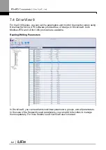


7.2.4 Command Loss Protective Operation
Configure the command loss decision standards and protective operations run when a
communication problem lasts for a specified period of time.
Command Loss Protective Operation Setting Details
Code and
Features
Description
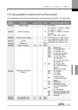
Pr.12 Lost Cmd
Mode,
Pr.13 Lost Cmd
Time
Select the operation to run when a communication error has occurred
and lasted exceeding the time set at Pr.13.
Configuration
Function
0
None
The speed command immediately becomes the
operation frequency without any protection
function.
1
Free-
Run
The inverter blocks output. The motor performs in
free-run condition.
2
Dec
The motor decelerates and then stops.
3
Hold
Input
The inverter continues in the speed command
input before the loss of speed.
4
Hold
Output
The inverter continues in the operation frequency
before the loss of speed.
5
Lost
Preset
The inverter operates at the frequency set at Pr.
14 (Lost Preset F).
7.2.5 Setting Virtual Multi-Function Input
Multi-function input can be controlled using a communication address (0h0385). Set
codes CM.70
–77 to the functions to operate, and then set the BIT relevant to the
function to 1 at 0h0322 to operate it. Virtual multi-function operates independently
from In.65
–69 analog multi-function inputs and cannot be set redundantly. Virtual
multi-function input can be monitored using CM.86 (Virt Dl Status). Before you
configure the virtual multi-function inputs, set the DRV code according to the
command source.
Group Code
Name
Setting
Setting Range
Unit
CM
70
–77
Communication multi-
function input x
0
None
0
–49
-
86
Communication multi-
function input monitoring
-
-
-
-
Example
: When sending an Fx command by controlling virtual multi-function input in
the common area via Int485, set CM.70 to FX. Then, assign a 0h0001 value to the
communication address 0h0322 to operate the forward direction operation (Fx)
feature.
Summary of Contents for G100
Page 14: ......
Page 16: ...5 5 7 5 kW 3 Phase ...
Page 32: ...0 4 0 8 kW 1 5 2 2 kW 4 0 kW ...
Page 48: ......
Page 68: ......
Page 81: ......
Page 100: ......
Page 116: ...trips automatic Reset Restart is not attempted and the Fire Mode Count is not increased ...
Page 118: ......
Page 130: ... Terminal connections for 3 wire operation 3 wire operation ...
Page 140: ... PID control block diagram ...
Page 165: ...Code and Features Description Code Description continuous rating ...
Page 170: ......
Page 186: ... Displayed as on the Keypad ...
Page 200: ...provided signal output at 150 36 sec ...
Page 216: ...Code and Features Description delay time delay time ...
Page 219: ......
Page 237: ......
Page 253: ......
Page 295: ......
Page 314: ......
Page 335: ...Manual Revision History Revision History No Date Edition Changes 1 2019 01 First Release ...


