


4.17 2
nd
Operation Mode
Apply two types of operation modes and switch between them as required. For both
the first and second command source, set the frequency after shifting operation
commands to the multi-function input terminal. Mode switching can be used to stop
remote control during an operation using the communication option and to switch
operation mode to operate via the local panel, or to operate the inverter from another
remote control location.
Select one of the multi-function terminals from codes In.65
–69 and set the parameter
value to 15 (2nd Source).
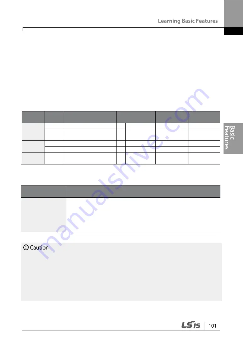
Group
Code
Name
Setting
Setting
Range
Unit
Operatio
n
drv
Command Source
1 Fx/Rx-1
0
–4
-
Frq
Frequency reference
source
2 V1
0
–8
-
bA
04
2nd command source 0 Keypad
0
–4
-
05
2nd frequency source 0 KeyPad-1
0
–8
-
In
65
–69
Px terminal setting
options
15 2nd Source
0
–52
-
2nd Operation Mode Setting Details
Code and
Features
Description
bA.04 Cmd 2nd
Src
bA.05 Freq 2nd
Src
If signals are provided to the multi-function terminal set as the 2nd
command source (2nd Source), the operation can be performed
using the set values from bA.04
–05 instead of the set values from
the drv and Frq codes in the Operation group.
The 2nd command source settings cannot be changed while
operating with the 1st command source (Main Source).
•
When setting the multi-function terminal to the 2nd command source (2nd Source) and
input (On) the signal, operation state is changed because the frequency setting and the
Operation command will be changed to the 2nd command. Before shifting input to the
multi-function terminal, ensure that the 2nd command is correctly set. Note that if the
deceleration time is too short or inertia of the load is too high, an overvoltage fault trip
may occur.
•
Depending on the parameter settings, the inverter may stop operating when you switch
the command modes.
Summary of Contents for G100
Page 14: ......
Page 16: ...5 5 7 5 kW 3 Phase ...
Page 32: ...0 4 0 8 kW 1 5 2 2 kW 4 0 kW ...
Page 48: ......
Page 68: ......
Page 81: ......
Page 100: ......
Page 116: ...trips automatic Reset Restart is not attempted and the Fire Mode Count is not increased ...
Page 118: ......
Page 130: ... Terminal connections for 3 wire operation 3 wire operation ...
Page 140: ... PID control block diagram ...
Page 165: ...Code and Features Description Code Description continuous rating ...
Page 170: ......
Page 186: ... Displayed as on the Keypad ...
Page 200: ...provided signal output at 150 36 sec ...
Page 216: ...Code and Features Description delay time delay time ...
Page 219: ......
Page 237: ......
Page 253: ......
Page 295: ......
Page 314: ......
Page 335: ...Manual Revision History Revision History No Date Edition Changes 1 2019 01 First Release ...


