Chapter 3 Installation and Wiring
XBC E-Type Main Unit
3-2
Ver. 1
3.1.1 Safety Instructions when designing PLC system
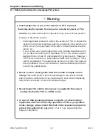
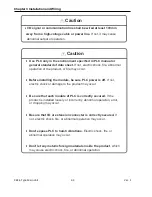
Install protection circuit on the exterior of PLC to protect
the whole control system from any error in external power or PLC
module.
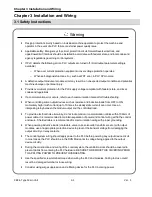
Any abnormal output or operation may cause serious problem
in safety of the whole system.
-
Install applicable protection unit on the exterior of PLC to protect the
system from physical damage such as emergency stop switch, prot
ection circuit, the upper/lower limit switch, forward/reverse interlock
circuit, etc.
-
If any system error (watch-dog timer error, module installation error,
etc.) is detected during CPU operation in PLC, the whole output is
designed to be turned off and stopped for system safety. However, i
f CPU error is caused on output device itself, such as relay or TR, it
cannot be detected. The output may be kept on, which may cause s
erious problems. It is recommended to install an additional circuit to
monitor the output status.
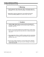
Never connect a load greater than the module’s output current
rating.
This could result in permanent damage to the output module
and a machine malfunction. Use mechanical or solid-state interposing
relay when necessary to prevent module damage.
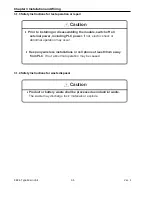
Never design the control where power is applied to the output
modules before the PLC is in RUN mode.
In case of data exchange between computer, or other external
equipment, and PLC to alter any operation of PLC (e.g. operation
mode change), please install interlock in the sequence program to
protect the system from any error
. If not, it may cause abnormal
output or operation.
Warning
Summary of Contents for XBC-DN10E
Page 1: ......
Page 10: ...Table of Contents Table of Contents 6 10 10 CLEAR ALL PLC 29...

