Chapter 4 CPU Specifications
XBC E-Type Main Unit
4-10
Ver. 1
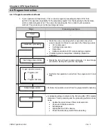
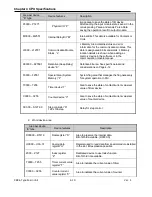
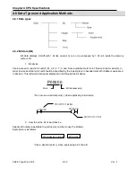
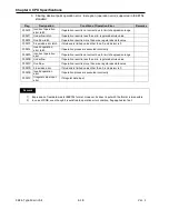
Area per device
Device features
Description
“E” type
P0000 ~ P127f
Physical I/O “P”
Image area to save the state of I/O device.
After reading the input module state, saves it in the
corresponding P area and sends P area Data
saving the operation result to output module.
M0000 ~ M255f
Internal Relay Bit “M”
Internal Bits. This data is available for Contacts or
Coils.
L0000 ~ L1279f
Communication Module
Status “L”
L Memory Area contains status and error
information for the communication modules. This
data is designated in bits and words. L Memory
location details are shown when adding a L
memory device in the software or in the
communication module manual.
K00000 ~ K2559f
Retentive (Keep Relay)
device “K”
Retentive bit area. See specific details and
considerations on Page 4-12
F0000 ~ F255f
Special Area (System
Memory) “F”
System flag area that manages the flag necessary
for system operation in PLC.
T0000 ~ T255
Timer device “T”
Area to save the state of contact/current value/set
value of timer device
C0000 ~ C255
Counter device “C”
Area to save the state of contact/current value/set
value of counter device
S00.00 ~ S127.99
Step controller “S”
128 x 100 step
Relay for step control
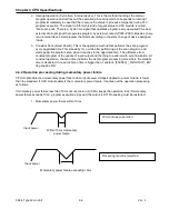
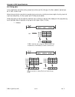
2. Word device area
Area per device
Device features
Description
“E” type
D00000 ~ D5119
Data register “D”
Area to preserve the internal data.
Bit of Word available. (D0000.0)
U00.00 ~ U0A.31
Analog data
register “U”
Register used to read data from special module installed
in the slot. Bit expression possible
Z000 ~ Z127
Index register
“Z”
Dedicated device to use Index function
Bit of Word not available.
T0000 ~ T255
Timer current value
register “T”
Area to indicate the current value of timer
C0000 ~ C255
Counter current
value register “C”
Area to indicate the current value of counter
Summary of Contents for XBC-DN10E
Page 1: ......
Page 10: ...Table of Contents Table of Contents 6 10 10 CLEAR ALL PLC 29...

