Chapter 3 Installation and Wiring
XBC E-Type Main Unit
3-1
Ver. 1
Chapter 3 Installation and Wiring
3.1 Safety Instructions
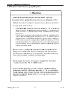
Warning
Design protection circuitry based on individual machine operation to protect the machine and
operator in the event of a PLC failure or external power quality issue.
Applicable safety: Emergency stop circuit, protection circuit, forward/reverse interlock, and
upper/lower limit interlock should be installed in accordance with federal, state, and local codes and
agency regulations governing control systems.
If PLC detects the following errors, PLC outputs are turned off. (Hold output parameter setting is
available)
o
When over current protection equipment or over voltage protection operates.
o
When self-diagnosis function error, such as WDT error, in PLC CPU occurs.
A defective output module or module error may result in an unexpected output condition and potential
machine damage or personal injury.
Provide overcurrent protection for the PLC supply voltage compliant with federal, state, and local
codes and regulations
If a communication error occurs, refer to each communication manual for troubleshooting.
When controlling some output devices such as resistive and inductive loads from OFF to ON,
momentary high inrush current (up to 10 times the steady state current) can occur. Use an
interposing relay between the module output and the controlled load.
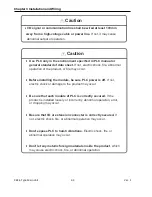
To provide electrical noise immunity, do not route control or communication cables within 100mm of
power cable. It is recommended to maintain separation of power and control wiring within the control
enclosure. Shielded cable is recommended for communication wiring with proper grounding.
When powering inductive loads (contactors, valve coils, solenoids, transformers, etc.) with output
modules, use an appropriate protection device to prevent the transient voltage from damaging the
output circuitry or relay contacts.
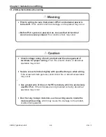
The control system wiring should apply power to the PLC before powering any output device circuit.
In most cases, the PLC should be in the RUN Mode prior to voltage being applied to the output
device circuitry.
During the construction and wiring of the control system, the ventilation slots should be covered to
prevent debris from entering the PLC hardware. BE SURE TO REMOVE THIS COVERING PRIOR
TO APPLYING POWER TO PREVENT OVERHEATING.
Use the specified screw terminal torque when wiring the PLC and modules. Failing to do so could
result in a damaged terminal or loose wiring.
Consider using surge suppression and a filtering device for the PLC incoming power
Summary of Contents for XBC-DN10E
Page 1: ......
Page 10: ...Table of Contents Table of Contents 6 10 10 CLEAR ALL PLC 29...

