Chapter 5. Power Supply / CPU
5-
10
•
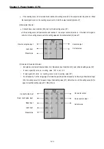
If the counting value (CV) increments and reaches the setting value (PV), the output contact (Q) turns on. When
the reset signal is turn on, the counting value is set to 0’ and the output contact (Q) turns off.
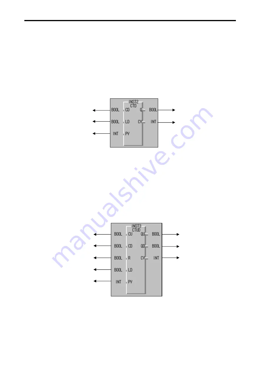
(2) Decrement Counter
•
It should have input condition (CD), load (LD) and setting value (PV).
•
If the counting value (CV) decrements and reaches 0’, the output contact (Q) turns on. If the load (LD) signal is
turned on, the counting value is set to the setting value and the output contact (Q) turns off.
(3) Increment / Decrement Counter
• It should have Increment input condition (CU); Decrement input condition (CD), load (LD) and setting value (PV).
• If reset signal (R) turns on, counting value (CV) is set to 0.
• If load signal (LD) turns on; counting value is set to setting value (PV).
• It is increased by 1 at the rising edge of increment input (CU) and decreased by 1 at the edge of decrement input
(CD). If counting value (CV) is equal or larger than setting value (PV), QU will be on, and if counting value (CV) is
equal or less than setting value (PV), QD will be on.
Current value
Counter output
Preset value
Load input
Down count pulse input
Current value
Down counter output
Load input
Up counter output
Reset input
Down count pulse input
Up count pulse input
Preset value
Summary of Contents for GLOFA G7M-DR20U
Page 28: ...Chapter 4 Names of Parts 4 3 2 G7M DRT60U N 3 G7M DT60U N 4 G7M DT60U P...
Page 29: ...Chapter 4 Names of Parts 4 4 5 G7M DR60U DC 6 G7M DRT60U N DC 7 G7M DT60U N DC...
Page 31: ...Chapter 4 Names of Parts 4 6 3 G7M DT40U N 4 G7M DT40U P 5 G7M DR40U DC...
Page 32: ...Chapter 4 Names of Parts 4 7 6 G7M DRT40U N DC 7 G7M DT40U N DC 8 G7M DT40U P DC...
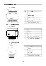
Page 33: ...Chapter 4 Names of Parts 4 8 4 1 3 30 point main unit 1 G7M DR30U 2 G7M DRT30U N 3 G7M DT30U N...
Page 34: ...Chapter 4 Names of Parts 4 9 4 G7M DT30U P 5 G7M DR30U DC 6 G7M DRT30U N DC...
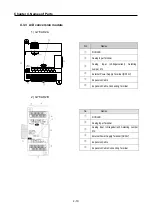
Page 36: ...Chapter 4 Names of Parts 4 11 2 G7M DRT20U N 3 G7M DT20U N 4 G7M DT20U P...
Page 37: ...Chapter 4 Names of Parts 4 12 5 G7M DR20U DC 6 G7M DRT20U N DC 7 G7M DT20U N DC...
Page 38: ...Chapter 4 Names of Parts 4 13 8 G7M DT20U P DC...
Page 159: ...Chapter 7 Usage of Various Functions 7 52 c Program...
Page 183: ...Chapter 7 Usage of Various Functions 7 76 c Program...
Page 253: ...Chapter 8 Communication Functions 8 27 b When uses Ch 1 Built in RS 485...
Page 356: ...Appendix 1 System Definitions App1 9 6 Position Parameter...
Page 357: ...Appendix 1 System Definitions App1 10 7 High Speed Counter Parameter...

