
Chapter 8. Communication Functions
8-87
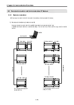
8.4.4 Example
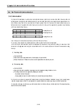
No Protocol Communication is useful to send or receive the unfixed data. This example assumes that an electrical weighing machine
sends unfixed data. GM7U can communicate with it using No Protocol Communication.
For No Protocol Communication, one of following end condition is designated. One is the size of the received data, and the other is the
the received data setting that is the some with pre-defined data.
This example assumes that the received data’s tail is EOT. If there is no tail in the received data, all of the received data must be
registered first in the DRCV function block.
Assume that the received data from a barcode is as follow.
“ENQ (1Byte) + Station No.(1Byte’) + Weighing data(1~10 Words) + EOT(1Byte)”
When the above frame is received, the receiving condition format is set as h0104, and the moment when EOT is received the received
framed is saved into the designated device. It checks the station and the data size and decides whether to use the received data. After
that, it sends the data using the DSND function block when it is needed to respond.
Assume that the sending data format is as follow.
“ACK (1Byte) + Station No.(1Byte’) + OK(2Bytes) + EOT(1Byte)”
In this example describes when the data range (1~10 word) is 1 word.
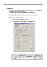
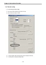
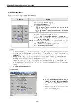
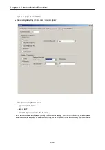
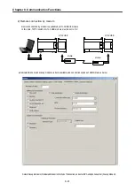
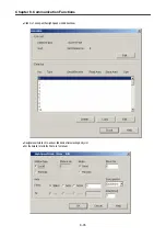
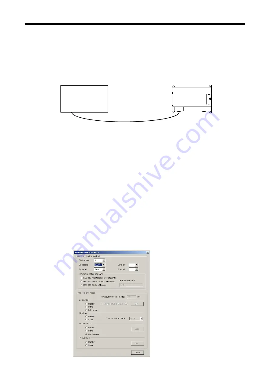
1) Communication parameter setting
•
Open a new project file from GMWIN, and select ‘GM7U’ for the PLC type.
•
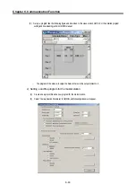
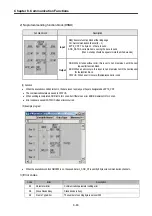
Designate baud rate, data bit, parity bit, stop bit, and protocol in ‘Communication method’.
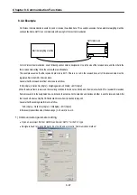
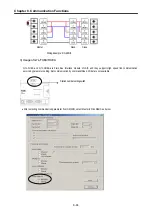
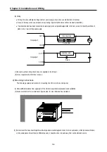
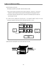
GM7U Main unit
Electrical weighing machine
Summary of Contents for GLOFA G7M-DR20U
Page 28: ...Chapter 4 Names of Parts 4 3 2 G7M DRT60U N 3 G7M DT60U N 4 G7M DT60U P...
Page 29: ...Chapter 4 Names of Parts 4 4 5 G7M DR60U DC 6 G7M DRT60U N DC 7 G7M DT60U N DC...
Page 31: ...Chapter 4 Names of Parts 4 6 3 G7M DT40U N 4 G7M DT40U P 5 G7M DR40U DC...
Page 32: ...Chapter 4 Names of Parts 4 7 6 G7M DRT40U N DC 7 G7M DT40U N DC 8 G7M DT40U P DC...
Page 33: ...Chapter 4 Names of Parts 4 8 4 1 3 30 point main unit 1 G7M DR30U 2 G7M DRT30U N 3 G7M DT30U N...
Page 34: ...Chapter 4 Names of Parts 4 9 4 G7M DT30U P 5 G7M DR30U DC 6 G7M DRT30U N DC...
Page 36: ...Chapter 4 Names of Parts 4 11 2 G7M DRT20U N 3 G7M DT20U N 4 G7M DT20U P...
Page 37: ...Chapter 4 Names of Parts 4 12 5 G7M DR20U DC 6 G7M DRT20U N DC 7 G7M DT20U N DC...
Page 38: ...Chapter 4 Names of Parts 4 13 8 G7M DT20U P DC...
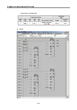
Page 159: ...Chapter 7 Usage of Various Functions 7 52 c Program...
Page 183: ...Chapter 7 Usage of Various Functions 7 76 c Program...
Page 253: ...Chapter 8 Communication Functions 8 27 b When uses Ch 1 Built in RS 485...
Page 356: ...Appendix 1 System Definitions App1 9 6 Position Parameter...
Page 357: ...Appendix 1 System Definitions App1 10 7 High Speed Counter Parameter...


