


Chapter 7. Usage of Various Functions
7-37
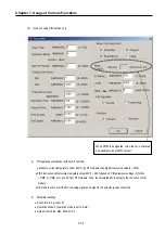
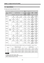
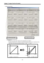
(3)
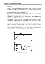
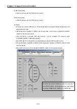
In case of using combined function of PID operation and auto tuning
(a)
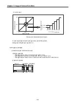
PID operation explanation (with A/T function)
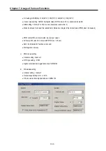
•
Measure current temperature by RTD module then digital conversion value(0 ~ 4000) is stored.
•
PID7AT instruction will calculate manipulate value (MV : 0 ~ 4000) based on the SV and PV from RTD module
and output the value in range of 0~4000 to the D/A conversion module.
•
The END bit of auto tuning status device will be 1 when the auto tuning is completed, and the calculate P, I, D
constants are saved respectively in the designated value. These values become the P, I, D control constant.
Program to execute the PID operation when the END bit becomes 1.
•
D/A conversion modules convert the manipulate value to analog signal (4~20mA) and input it to the actuator.
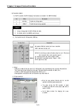
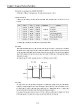
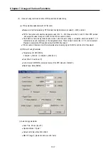
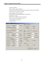
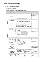
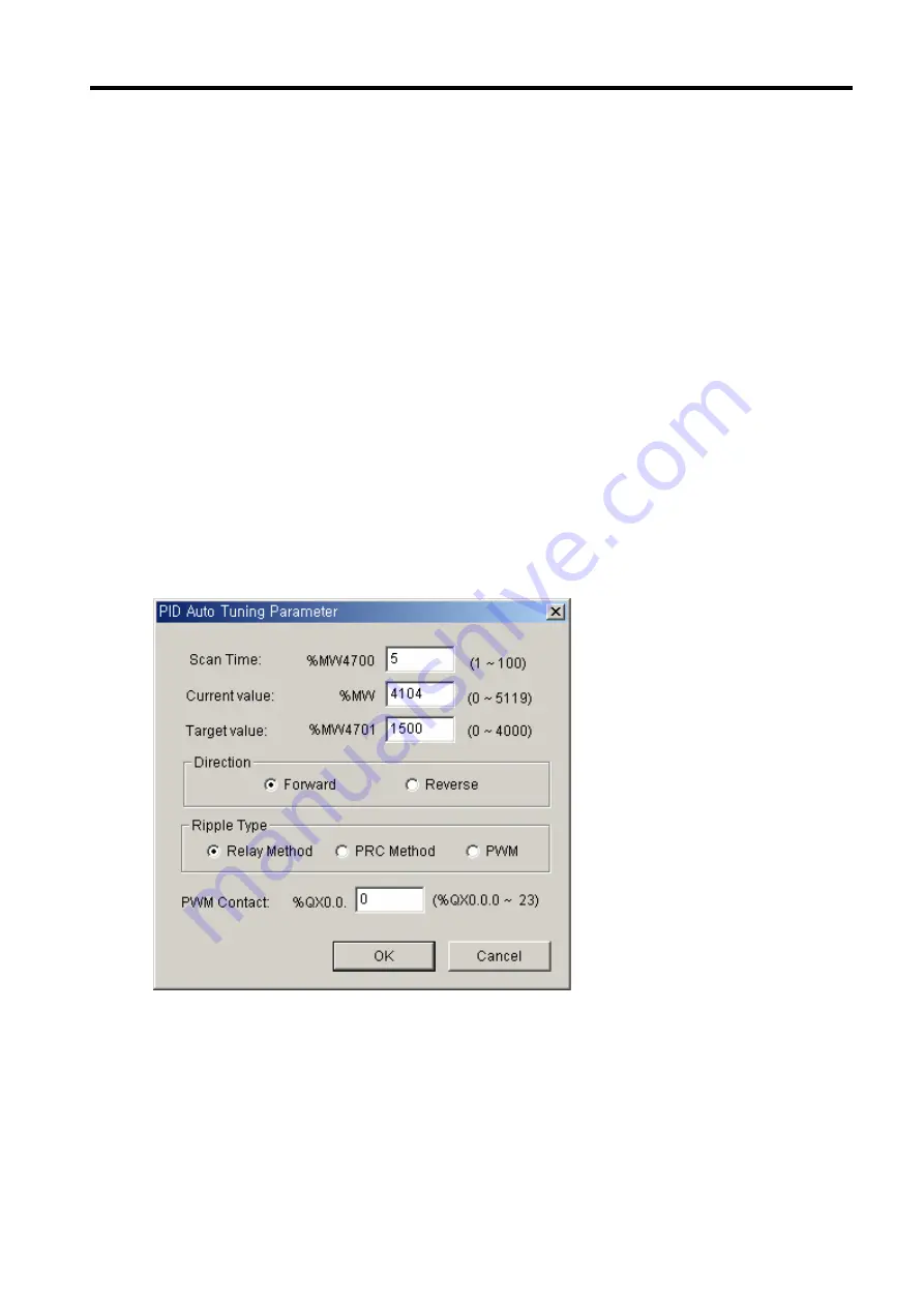
(b) PID Auto Tuning Parameter
•
Target value (for G7F-RD2A)
- 1300(60
℃
),1350(70
℃
),1400(80
℃
),1500(100
℃
)
•
Scan Time: 0.5 sec(input ‘5’)
•
Current value: %MW4104 (conversion value of the RTD module’s channel 0)
•
Ripple Type: Relay Method
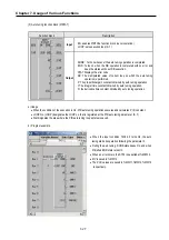
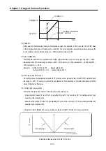
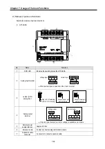
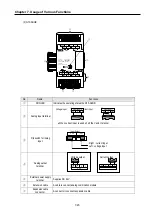
(c) Auto tuning parameters
•
Scan Time: 0.5 sec (input ‘5’)
•
Operation Mode: 0 (Auto)
•
Output Limit Value: Max: 4000, Min: 0
•
Man OP range: 0 (Operation mode is set to ‘Auto’)
Summary of Contents for GLOFA G7M-DR20U
Page 28: ...Chapter 4 Names of Parts 4 3 2 G7M DRT60U N 3 G7M DT60U N 4 G7M DT60U P...
Page 29: ...Chapter 4 Names of Parts 4 4 5 G7M DR60U DC 6 G7M DRT60U N DC 7 G7M DT60U N DC...
Page 31: ...Chapter 4 Names of Parts 4 6 3 G7M DT40U N 4 G7M DT40U P 5 G7M DR40U DC...
Page 32: ...Chapter 4 Names of Parts 4 7 6 G7M DRT40U N DC 7 G7M DT40U N DC 8 G7M DT40U P DC...
Page 33: ...Chapter 4 Names of Parts 4 8 4 1 3 30 point main unit 1 G7M DR30U 2 G7M DRT30U N 3 G7M DT30U N...
Page 34: ...Chapter 4 Names of Parts 4 9 4 G7M DT30U P 5 G7M DR30U DC 6 G7M DRT30U N DC...
Page 36: ...Chapter 4 Names of Parts 4 11 2 G7M DRT20U N 3 G7M DT20U N 4 G7M DT20U P...
Page 37: ...Chapter 4 Names of Parts 4 12 5 G7M DR20U DC 6 G7M DRT20U N DC 7 G7M DT20U N DC...
Page 38: ...Chapter 4 Names of Parts 4 13 8 G7M DT20U P DC...
Page 159: ...Chapter 7 Usage of Various Functions 7 52 c Program...
Page 183: ...Chapter 7 Usage of Various Functions 7 76 c Program...
Page 253: ...Chapter 8 Communication Functions 8 27 b When uses Ch 1 Built in RS 485...
Page 356: ...Appendix 1 System Definitions App1 9 6 Position Parameter...
Page 357: ...Appendix 1 System Definitions App1 10 7 High Speed Counter Parameter...


