


Chapter 7. Usage of Various Functions
7-78
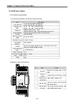
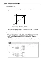
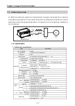
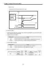
2) Output specification (QX0.0.0, QX0.0.1, QX0.0.2, QX0.0.3)
Signal Name
Rated load
voltage
Load voltage range
Max. load current
Max. voltage drop during On
DC 12/24V
DC 10.2 26.4V
∼
100
㎃
DC 0.3 V or less
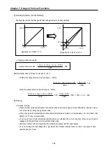
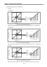
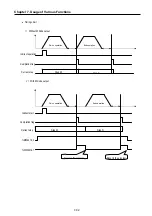
Forward direction
Reverse direction
Positioning
(CW / CCW)
QX0.0.0 ~.1
QX0.0.2 ~.3
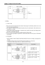
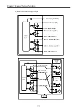
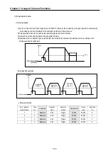
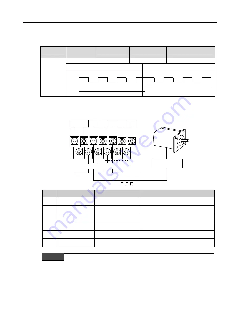
3) Names of wiring terminal
No.
Terminal No.
Name
Usage
①
QX0.0.0
Pulse output (Ch0)
Pulse output terminal
②
QX0.0.1
Pulse output (Ch1)
Pulse output terminal
③
QX0.0.2
Direction output (Ch0)
Direction output terminal
④
QX0.0.3
Direction output (Ch1)
Direction output terminal
⑤
COM0,COM1,COM2
Common
Pulse output common terminal
⑥
P
24V
External 24V supply terminal
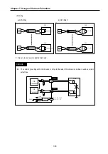
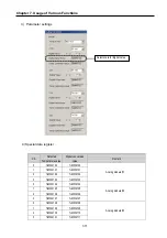
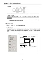
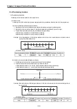
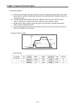
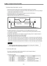
Positioning function is sensitive to the external noise and should be handled with special care.
1)
Be sure to use shielded twisted pair cables. Also provide Class 3 grounding
2)
Do not run a twisted pair cable in parallel with power cables or other I/O lines which may generate noise
3) Before applying a power source for pulse generator, be sure to use a noise-protected power supply
⑤
⑤
②
Pulse output
①
AC220V
FG COM0
P40
COM1
P41
COM2
P42
Direction pulse
Motor driver
Stepping motor
COM3
P43
P
COM
P44
⑥
③
⑤
④
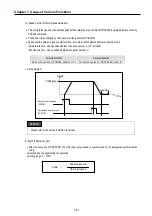
REMARK
Summary of Contents for GLOFA G7M-DR20U
Page 28: ...Chapter 4 Names of Parts 4 3 2 G7M DRT60U N 3 G7M DT60U N 4 G7M DT60U P...
Page 29: ...Chapter 4 Names of Parts 4 4 5 G7M DR60U DC 6 G7M DRT60U N DC 7 G7M DT60U N DC...
Page 31: ...Chapter 4 Names of Parts 4 6 3 G7M DT40U N 4 G7M DT40U P 5 G7M DR40U DC...
Page 32: ...Chapter 4 Names of Parts 4 7 6 G7M DRT40U N DC 7 G7M DT40U N DC 8 G7M DT40U P DC...
Page 33: ...Chapter 4 Names of Parts 4 8 4 1 3 30 point main unit 1 G7M DR30U 2 G7M DRT30U N 3 G7M DT30U N...
Page 34: ...Chapter 4 Names of Parts 4 9 4 G7M DT30U P 5 G7M DR30U DC 6 G7M DRT30U N DC...
Page 36: ...Chapter 4 Names of Parts 4 11 2 G7M DRT20U N 3 G7M DT20U N 4 G7M DT20U P...
Page 37: ...Chapter 4 Names of Parts 4 12 5 G7M DR20U DC 6 G7M DRT20U N DC 7 G7M DT20U N DC...
Page 38: ...Chapter 4 Names of Parts 4 13 8 G7M DT20U P DC...
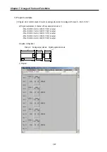
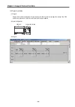
Page 159: ...Chapter 7 Usage of Various Functions 7 52 c Program...
Page 183: ...Chapter 7 Usage of Various Functions 7 76 c Program...
Page 253: ...Chapter 8 Communication Functions 8 27 b When uses Ch 1 Built in RS 485...
Page 356: ...Appendix 1 System Definitions App1 9 6 Position Parameter...
Page 357: ...Appendix 1 System Definitions App1 10 7 High Speed Counter Parameter...


