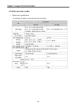


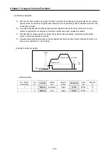

Chapter 7. Usage of Various Functions
7-75
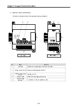
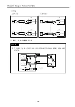
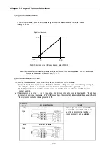
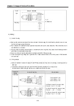
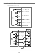
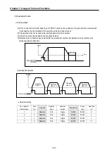
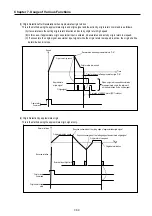
4-wired type
Method of Connection between Pt and RTD Input Module
*1: RTD (Pt100 or JPt1000)
*:2: Shielded wire - The shields of the RTD and shields of wire should be connected to the FG of the RTD input module.
REMARK
The difference between the resistance values of the wires used should be 1
Ω
or less, or the accuracy shown
in 1) Performance specification could not be satisfied.
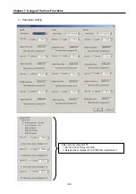
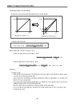
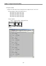
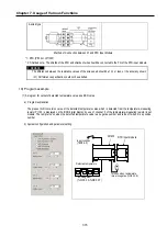
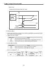
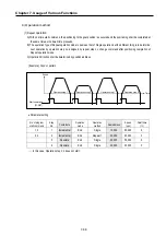
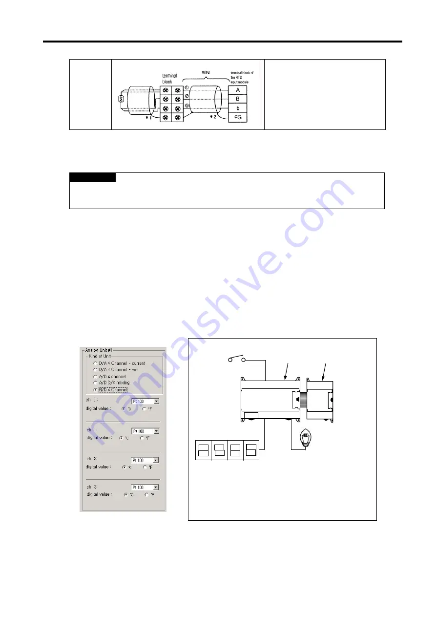
10) Program example
(1) A program for output of detected temperature value as a BCD value
a)
Program explanation
The present A/D conversion value of the detected temperature value which is detected from the temperature-measuring
resistor Pt 100 is displayed on the BCD digital display by use of channel 0 of the temperature-measuring resistor input
module. The lamp turns on when the detected temperature value is a negative number and turns off when it is a positive
number
b) System configuration and parameter setting
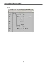
RTD input module
Turns on when temperature
value is negative (%QX0.0.8)
BCD segment
( %QX0.0.0~%QX0.0.7)
Detected temperature
Input condition
(%IX0.0.0)
COM0
Summary of Contents for GLOFA G7M-DR20U
Page 28: ...Chapter 4 Names of Parts 4 3 2 G7M DRT60U N 3 G7M DT60U N 4 G7M DT60U P...
Page 29: ...Chapter 4 Names of Parts 4 4 5 G7M DR60U DC 6 G7M DRT60U N DC 7 G7M DT60U N DC...
Page 31: ...Chapter 4 Names of Parts 4 6 3 G7M DT40U N 4 G7M DT40U P 5 G7M DR40U DC...
Page 32: ...Chapter 4 Names of Parts 4 7 6 G7M DRT40U N DC 7 G7M DT40U N DC 8 G7M DT40U P DC...
Page 33: ...Chapter 4 Names of Parts 4 8 4 1 3 30 point main unit 1 G7M DR30U 2 G7M DRT30U N 3 G7M DT30U N...
Page 34: ...Chapter 4 Names of Parts 4 9 4 G7M DT30U P 5 G7M DR30U DC 6 G7M DRT30U N DC...
Page 36: ...Chapter 4 Names of Parts 4 11 2 G7M DRT20U N 3 G7M DT20U N 4 G7M DT20U P...
Page 37: ...Chapter 4 Names of Parts 4 12 5 G7M DR20U DC 6 G7M DRT20U N DC 7 G7M DT20U N DC...
Page 38: ...Chapter 4 Names of Parts 4 13 8 G7M DT20U P DC...
Page 159: ...Chapter 7 Usage of Various Functions 7 52 c Program...
Page 183: ...Chapter 7 Usage of Various Functions 7 76 c Program...
Page 253: ...Chapter 8 Communication Functions 8 27 b When uses Ch 1 Built in RS 485...
Page 356: ...Appendix 1 System Definitions App1 9 6 Position Parameter...
Page 357: ...Appendix 1 System Definitions App1 10 7 High Speed Counter Parameter...


