

Appendix 2. Flag Lists
App2-6
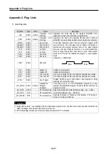
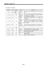
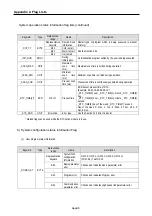
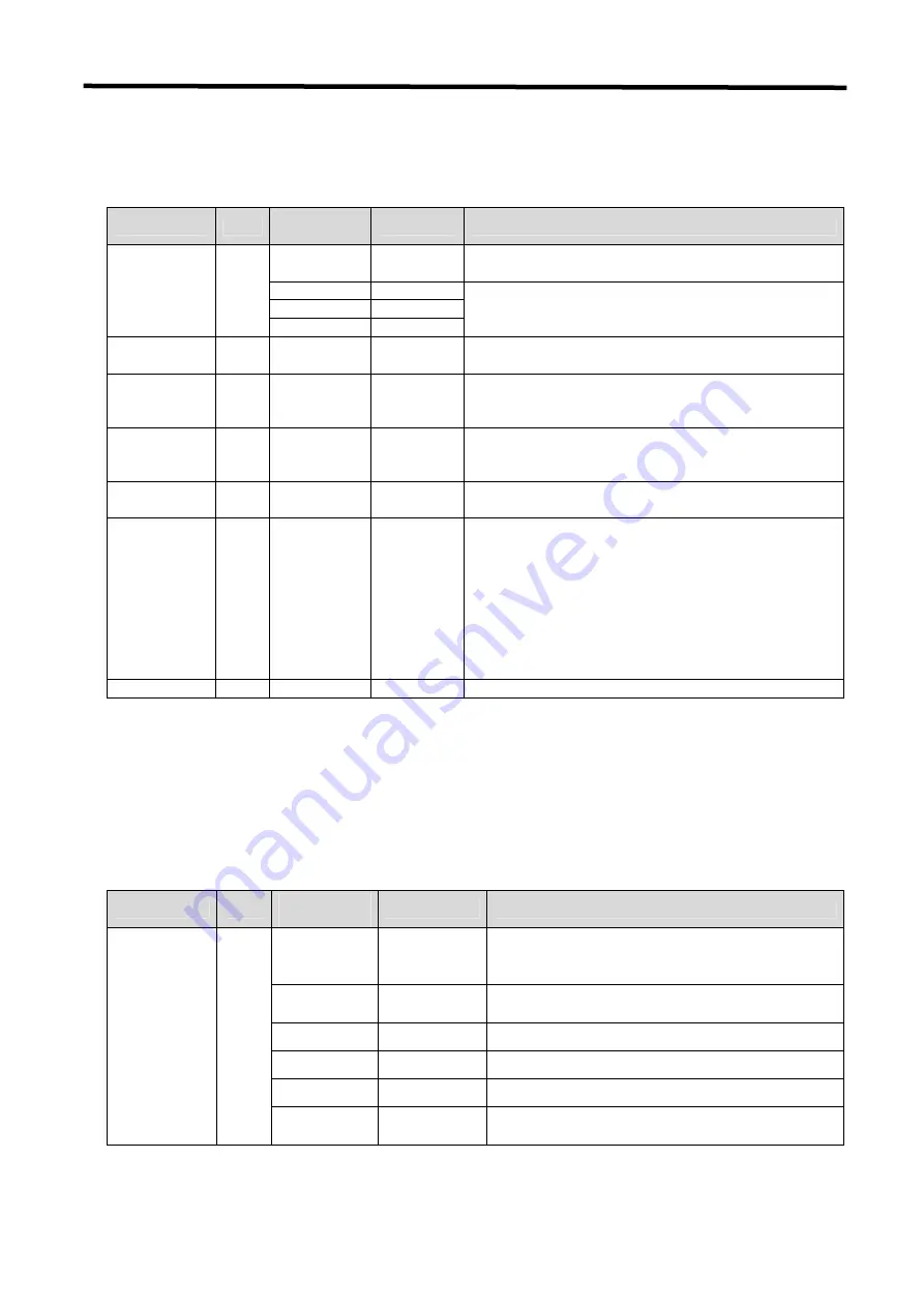
System operation status information flag lists (continued)
Keyword
Type
Data setting
range
Name
Description
Representative
keyword
Restart mode
information
Restart type of program which is being executed in present.
(History)
Bit 0
Cold restart
Bit 1
Warm restart
_RST_TY BYTE
Bit 2
Hot restart
See the Section 4.5.1
_INIT_RUN BOOL
-
During
initialization
An initialization program written by the user is being executed
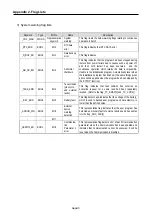
_SCAN_MAX UNIT
-
Maximum
scan time
(ms)
Maximum scan time is written during operation.
_SCAN_MIN UNIT
-
Minimum
scan time
(ms)
Minimum scan time is written during operation.
_SCAN_CUR UNIT
-
Present scan
time (ms)
Present scan time is continuously updated during operation.
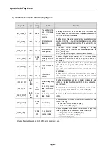
_RTC_TIME[n]*
BCD
N: 0 to 7
Present time
BCD data of present time of RTC
(Example: 96-01-12-00-00-00-XX)
_RTC _TIME[0]: year, _RTC _TIME[1]: month, _RTC _TIME[2]:
day,
_RTC _TIME[3]: hour, _RTC _TIME[4]: minute, _RTC _TIME[5]:
second,
_RTC _TIME[6]: day of the week, _RTC _TIME[7]: unused
Day of the week: 0: Mon., 1: Tue., 2: Wed., 3:Thur., 4:Fri., 5:
Sat., 6:Sun.
_SYS_ERR
UNIT
Error code
Error type
See the Section 12.5 Error Code List
* Marked flags can be used while the RTC option module is in use.
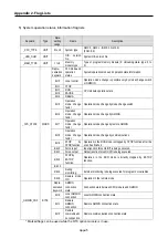
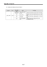
6) System configuration status information Flag
(1)
User program status information
Keyword
Type
Data setting
range
Name
Description
Representative
keyword
System S/W
configuration
information
GM1: 0, GM2: 1, (GM3: 2, GM4: 3, GM%: 4)
(FSM: 5,6), Twofold: 16
Bit 0
Basic parameter
error
Checks and indicates Basic parameter error
- -
-
Bit 2
Program error
Checks and indicates Program error
- -
-
_DOMAN_ST BYTE
Bit 4
Communication
parameter error
Checks and indicates High speed link parameter error
Summary of Contents for GLOFA G7M-DR20U
Page 28: ...Chapter 4 Names of Parts 4 3 2 G7M DRT60U N 3 G7M DT60U N 4 G7M DT60U P...
Page 29: ...Chapter 4 Names of Parts 4 4 5 G7M DR60U DC 6 G7M DRT60U N DC 7 G7M DT60U N DC...
Page 31: ...Chapter 4 Names of Parts 4 6 3 G7M DT40U N 4 G7M DT40U P 5 G7M DR40U DC...
Page 32: ...Chapter 4 Names of Parts 4 7 6 G7M DRT40U N DC 7 G7M DT40U N DC 8 G7M DT40U P DC...
Page 33: ...Chapter 4 Names of Parts 4 8 4 1 3 30 point main unit 1 G7M DR30U 2 G7M DRT30U N 3 G7M DT30U N...
Page 34: ...Chapter 4 Names of Parts 4 9 4 G7M DT30U P 5 G7M DR30U DC 6 G7M DRT30U N DC...
Page 36: ...Chapter 4 Names of Parts 4 11 2 G7M DRT20U N 3 G7M DT20U N 4 G7M DT20U P...
Page 37: ...Chapter 4 Names of Parts 4 12 5 G7M DR20U DC 6 G7M DRT20U N DC 7 G7M DT20U N DC...
Page 38: ...Chapter 4 Names of Parts 4 13 8 G7M DT20U P DC...
Page 159: ...Chapter 7 Usage of Various Functions 7 52 c Program...
Page 183: ...Chapter 7 Usage of Various Functions 7 76 c Program...
Page 253: ...Chapter 8 Communication Functions 8 27 b When uses Ch 1 Built in RS 485...
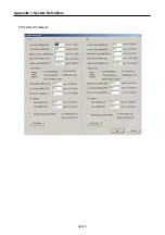
Page 356: ...Appendix 1 System Definitions App1 9 6 Position Parameter...
Page 357: ...Appendix 1 System Definitions App1 10 7 High Speed Counter Parameter...


