


Chapter 9. Installation and Wiring
9-1
Chapter 9. Installation and Wiring
9.1 Installation
9.1.1 Installation
environment
This unit has high reliability regardless of its installation environment, but be sure to check the following for system reliability.
1) Environment requirements
Avoid installing this unit in locations which are subjected or exposed to:
(1) Water leakage and dust.
(2) Continuous shocks or vibrations.
(3) Direct sunlight.
(4) Dew condensation due to rapid temperature change.
(5) Higher or lower temperatures outside the range of 0 to 55
℃
(6) Relative humidity outside the range of 5 to 95
℃
(7) Corrosive or flammable gases
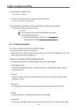
2) Precautions during installing
(1) During drilling or wiring, do not allow any wire scraps to enter into the PLC.
(2) Install it on locations that are convenient for operation.
(3) Make sure that it is not located on the same panel that high voltage equipment located.
(4) Make sure that the distance from the walls of duct and external equipment be 50mm or more.
(5) Be sure to be grounded to locations that have good ambient noise immunity.
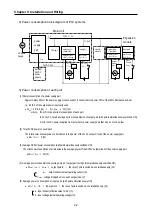
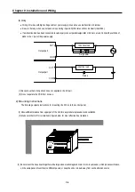
3) Heat protection design of control box
(1) When installing the PLC in a closed control box, be sure to design heat protection of control box with consideration of the
heat generated by the PLC itself and other devices.
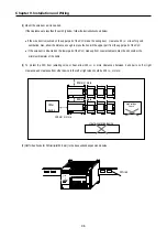
(2) It is recommended that filters or closed heat exchangers be used.
(3) The following shows the procedure for calculating the PLC system power consumption.
Summary of Contents for GLOFA G7M-DR20U
Page 28: ...Chapter 4 Names of Parts 4 3 2 G7M DRT60U N 3 G7M DT60U N 4 G7M DT60U P...
Page 29: ...Chapter 4 Names of Parts 4 4 5 G7M DR60U DC 6 G7M DRT60U N DC 7 G7M DT60U N DC...
Page 31: ...Chapter 4 Names of Parts 4 6 3 G7M DT40U N 4 G7M DT40U P 5 G7M DR40U DC...
Page 32: ...Chapter 4 Names of Parts 4 7 6 G7M DRT40U N DC 7 G7M DT40U N DC 8 G7M DT40U P DC...
Page 33: ...Chapter 4 Names of Parts 4 8 4 1 3 30 point main unit 1 G7M DR30U 2 G7M DRT30U N 3 G7M DT30U N...
Page 34: ...Chapter 4 Names of Parts 4 9 4 G7M DT30U P 5 G7M DR30U DC 6 G7M DRT30U N DC...
Page 36: ...Chapter 4 Names of Parts 4 11 2 G7M DRT20U N 3 G7M DT20U N 4 G7M DT20U P...
Page 37: ...Chapter 4 Names of Parts 4 12 5 G7M DR20U DC 6 G7M DRT20U N DC 7 G7M DT20U N DC...
Page 38: ...Chapter 4 Names of Parts 4 13 8 G7M DT20U P DC...
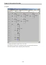
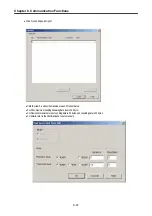
Page 159: ...Chapter 7 Usage of Various Functions 7 52 c Program...
Page 183: ...Chapter 7 Usage of Various Functions 7 76 c Program...
Page 253: ...Chapter 8 Communication Functions 8 27 b When uses Ch 1 Built in RS 485...
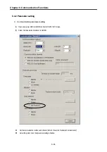
Page 356: ...Appendix 1 System Definitions App1 9 6 Position Parameter...
Page 357: ...Appendix 1 System Definitions App1 10 7 High Speed Counter Parameter...


