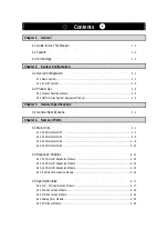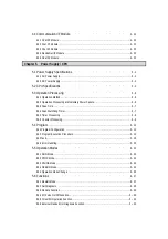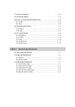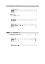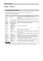
Chapter 1. General
1 - 5
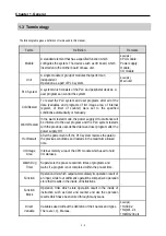
Terms
Definition
Remarks
Symbolic
Variable
Variables used after the user’s definition of their names and
types. Declarations as ‘INPUT_0’ = %IX0.0.2, ‘RESULT
= %MD1234’ makes INPUT_0 and RESULT be able to used
instead of %IX0.0.2 and %MD123 in programming.
GMWIN
A peripheral device for the GLOFA-GM series. It executes
program creation, edit, compile and debugging.
FAM
Abbreviation of the word ‘Factory Automation Monitoring S/W’.
It is used to call S/W packages for process supervision.
Task
It means startup conditions for a program. There are three
types of periodic task, internal contact task and external
contact task which starts by the input signals of external input
modules.
RTC
Abbreviation of ‘Real Time Clock’. It is used to call general IC
that contains clock function.
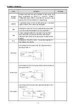
Sink Input
Current flows from the switch to the PLC input terminal if a
input signal turns on.
Source Input
Current flows from the PLC input terminal to the switch after an
input signal turns on.
Sink Output
Current flows from the load to the output terminal and the PLC
output turn on.
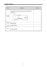
Output
Contact
Summary of Contents for GLOFA G7M-DR20U
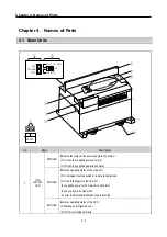
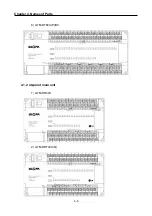
Page 28: ...Chapter 4 Names of Parts 4 3 2 G7M DRT60U N 3 G7M DT60U N 4 G7M DT60U P...
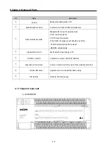
Page 29: ...Chapter 4 Names of Parts 4 4 5 G7M DR60U DC 6 G7M DRT60U N DC 7 G7M DT60U N DC...
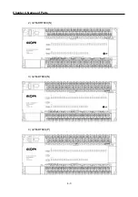
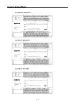
Page 31: ...Chapter 4 Names of Parts 4 6 3 G7M DT40U N 4 G7M DT40U P 5 G7M DR40U DC...
Page 32: ...Chapter 4 Names of Parts 4 7 6 G7M DRT40U N DC 7 G7M DT40U N DC 8 G7M DT40U P DC...
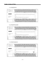
Page 33: ...Chapter 4 Names of Parts 4 8 4 1 3 30 point main unit 1 G7M DR30U 2 G7M DRT30U N 3 G7M DT30U N...
Page 34: ...Chapter 4 Names of Parts 4 9 4 G7M DT30U P 5 G7M DR30U DC 6 G7M DRT30U N DC...
Page 36: ...Chapter 4 Names of Parts 4 11 2 G7M DRT20U N 3 G7M DT20U N 4 G7M DT20U P...
Page 37: ...Chapter 4 Names of Parts 4 12 5 G7M DR20U DC 6 G7M DRT20U N DC 7 G7M DT20U N DC...
Page 38: ...Chapter 4 Names of Parts 4 13 8 G7M DT20U P DC...
Page 159: ...Chapter 7 Usage of Various Functions 7 52 c Program...
Page 183: ...Chapter 7 Usage of Various Functions 7 76 c Program...
Page 253: ...Chapter 8 Communication Functions 8 27 b When uses Ch 1 Built in RS 485...
Page 356: ...Appendix 1 System Definitions App1 9 6 Position Parameter...
Page 357: ...Appendix 1 System Definitions App1 10 7 High Speed Counter Parameter...

