


Chapter 5. Power Supply / CPU
5-24
5.5.2 STOP mode
In this mode, programs are not operated.
1) Processing when the operation mode changes
The output image area is cleared and output refresh is executed.
2) Operation processing contents
(1) I/O refresh is executed.
(2) Normal or abnormal operation and mounting conditions of the loaded module are checked.
(3) Communications service or other internal operations are processed.
5.5.3 PAUSE mode
In this mode, the program operation is temporarily stopped. If it returns to the RUN mode, the operation continues from
the state before the stop.
1) Processing when the operation mode changes
Data area and input image are not cleared and the operating conditions just before the mode change is maintain.
2) Operation processing contents
(1) I/O refresh is executed.
(2) Normal or abnormal operation and mounting conditions of the loaded module are checked.
(3) Communications service or other internal operations are processed.
5.5.4 DEBUG mode
In this mode, errors of a program are searched and the operation sequence is traced. Changing into this mode is only
possible in the STOP mode. In this mode, a program can be checked with examination on its execution state and
contents of each data.
1) Processing when the operation mode changes
[1] Data area is initialized at the starting time of the mode change complying with the restart mode, which has been set
on the parameters.
(2) The output image area is cleared and output refresh is executed.
2) Operation processing contents
(1) I/O refresh is executed by one time every scan.
(2) Communications service or other internal operations are processed.
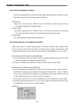
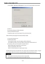
3) Operation method
(1) Execute the operation after the debug operation conditions have been set in the GMWIN.
(2) In task programs, each task can be specified to operation enable/disable.(For detailed operation method, refer to
the GMWIN User’s Manual Chapter 9 ‘Debugging’.
Summary of Contents for GLOFA G7M-DR20U
Page 28: ...Chapter 4 Names of Parts 4 3 2 G7M DRT60U N 3 G7M DT60U N 4 G7M DT60U P...
Page 29: ...Chapter 4 Names of Parts 4 4 5 G7M DR60U DC 6 G7M DRT60U N DC 7 G7M DT60U N DC...
Page 31: ...Chapter 4 Names of Parts 4 6 3 G7M DT40U N 4 G7M DT40U P 5 G7M DR40U DC...
Page 32: ...Chapter 4 Names of Parts 4 7 6 G7M DRT40U N DC 7 G7M DT40U N DC 8 G7M DT40U P DC...
Page 33: ...Chapter 4 Names of Parts 4 8 4 1 3 30 point main unit 1 G7M DR30U 2 G7M DRT30U N 3 G7M DT30U N...
Page 34: ...Chapter 4 Names of Parts 4 9 4 G7M DT30U P 5 G7M DR30U DC 6 G7M DRT30U N DC...
Page 36: ...Chapter 4 Names of Parts 4 11 2 G7M DRT20U N 3 G7M DT20U N 4 G7M DT20U P...
Page 37: ...Chapter 4 Names of Parts 4 12 5 G7M DR20U DC 6 G7M DRT20U N DC 7 G7M DT20U N DC...
Page 38: ...Chapter 4 Names of Parts 4 13 8 G7M DT20U P DC...
Page 159: ...Chapter 7 Usage of Various Functions 7 52 c Program...
Page 183: ...Chapter 7 Usage of Various Functions 7 76 c Program...
Page 253: ...Chapter 8 Communication Functions 8 27 b When uses Ch 1 Built in RS 485...
Page 356: ...Appendix 1 System Definitions App1 9 6 Position Parameter...
Page 357: ...Appendix 1 System Definitions App1 10 7 High Speed Counter Parameter...


