
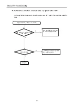
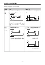
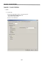


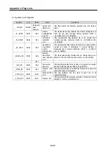
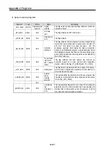
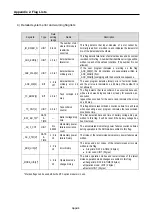
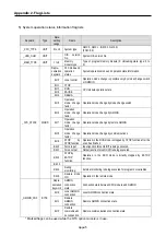
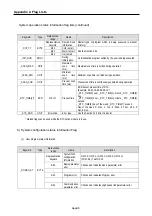
Appendix 1. System Definitions
App1-7
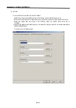
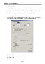
(5)
Stop bit: 1 or 2 bit(s)
(6)
Communication channel
•
RS-232C Null Modem or RS-422/485: Select this channel to communicate through GM7U base unit or Cnet I/F
module (G7L-CUEC).
•
RS-232C modem(Dedicated Line): Select this channel to communicate through Cnet I/F module (G7L-CUEB).
•
RS-232C dial-up modem: Select this channel to communicate dial-up modem for modem communication, using Cnet
I/F module (G7L-CUEB)
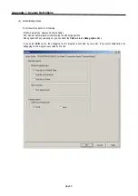
REMARK
RS-232C modem(Dedicated Line) and RS232C dial up modem communication can be executed under
RS-232C I/F module(G7L-CUEB)
(7) Master/slave: Select master to be major in the communications system.
(8) Time out
•
The value of default is 500ms.
•
Set the maximum cycle time for sending and receiving of the master PLC.
•
It may cause of communication error that lower setting value than maximum cycle time for sending and receiving.
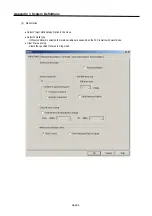
(9) Reading slave PLC status.
•
Select to read GM7U base unit status as slave designated. But do not choose this except for the monitoring of the
slave status. It may cause to drop down the communication speed.
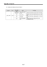
4) Special parameters
Summary of Contents for GLOFA G7M-DR20U
Page 28: ...Chapter 4 Names of Parts 4 3 2 G7M DRT60U N 3 G7M DT60U N 4 G7M DT60U P...
Page 29: ...Chapter 4 Names of Parts 4 4 5 G7M DR60U DC 6 G7M DRT60U N DC 7 G7M DT60U N DC...
Page 31: ...Chapter 4 Names of Parts 4 6 3 G7M DT40U N 4 G7M DT40U P 5 G7M DR40U DC...
Page 32: ...Chapter 4 Names of Parts 4 7 6 G7M DRT40U N DC 7 G7M DT40U N DC 8 G7M DT40U P DC...
Page 33: ...Chapter 4 Names of Parts 4 8 4 1 3 30 point main unit 1 G7M DR30U 2 G7M DRT30U N 3 G7M DT30U N...
Page 34: ...Chapter 4 Names of Parts 4 9 4 G7M DT30U P 5 G7M DR30U DC 6 G7M DRT30U N DC...
Page 36: ...Chapter 4 Names of Parts 4 11 2 G7M DRT20U N 3 G7M DT20U N 4 G7M DT20U P...
Page 37: ...Chapter 4 Names of Parts 4 12 5 G7M DR20U DC 6 G7M DRT20U N DC 7 G7M DT20U N DC...
Page 38: ...Chapter 4 Names of Parts 4 13 8 G7M DT20U P DC...
Page 159: ...Chapter 7 Usage of Various Functions 7 52 c Program...
Page 183: ...Chapter 7 Usage of Various Functions 7 76 c Program...
Page 253: ...Chapter 8 Communication Functions 8 27 b When uses Ch 1 Built in RS 485...
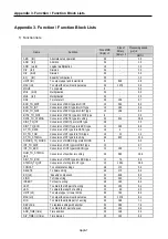
Page 356: ...Appendix 1 System Definitions App1 9 6 Position Parameter...
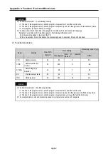
Page 357: ...Appendix 1 System Definitions App1 10 7 High Speed Counter Parameter...


