


Chapter 7. Usage of Various Functions
7-115
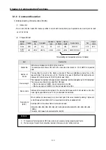
REMARK
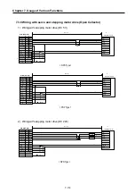
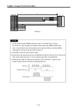
1 ) In case of VEXTA RK series, TIMMING output turns on when a motor rotates at every 7.2 degree.
For exact ‘return to origin’, we suggest you to configure ‘AND’ operation using TIMMING output and DOG
sensor. It may be different to each system features to return to origin by the DOG sensor without TIMMING
output signal (The rated input for the origin of GM7U is DC 24V.)
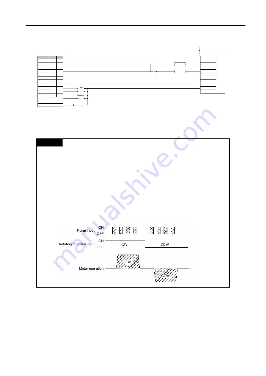
2) Using DC 24V, wire a proper resistor to driver in series.
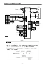
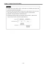
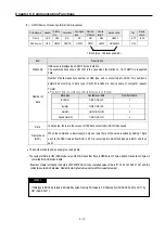
3) Input points for origin, approximate origin point, and upper/lower limit signal are fixed but, if they’re not used you
able to use them general input point. You can use emergency stop with the command(POSCTR)
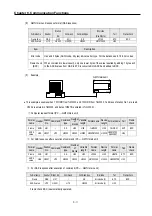
4) Positioning phase of GM7U is as follow: Set the input mode of a step mode driver to 1 phase input mode
because motor operation mode is determined by rotating direction input.
CW+
CW-
CCW+
CCW-
TIMING
COM
DC24V
Max : 2m
Stepping Motor Driver
Pulse
DC24V
P40 P41
Signal name
Ch0 Ch1
Direction
P42
P43
Common
COM0 COM1
Common
COM2 COM2
Input 0V
0V
0V
Origin
P04
P06
P05
P07
High Limit
P01
P03
Low limit
P00
P02
Emergency stop Input Point
Common
COM0(Input)
2K, 1/2W
2K,1/2W
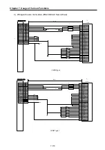
*2
* 1
G7M-D(R)T**U(P)
*3
*4
DOG
< PNP Type >
Summary of Contents for GLOFA G7M-DR20U
Page 28: ...Chapter 4 Names of Parts 4 3 2 G7M DRT60U N 3 G7M DT60U N 4 G7M DT60U P...
Page 29: ...Chapter 4 Names of Parts 4 4 5 G7M DR60U DC 6 G7M DRT60U N DC 7 G7M DT60U N DC...
Page 31: ...Chapter 4 Names of Parts 4 6 3 G7M DT40U N 4 G7M DT40U P 5 G7M DR40U DC...
Page 32: ...Chapter 4 Names of Parts 4 7 6 G7M DRT40U N DC 7 G7M DT40U N DC 8 G7M DT40U P DC...
Page 33: ...Chapter 4 Names of Parts 4 8 4 1 3 30 point main unit 1 G7M DR30U 2 G7M DRT30U N 3 G7M DT30U N...
Page 34: ...Chapter 4 Names of Parts 4 9 4 G7M DT30U P 5 G7M DR30U DC 6 G7M DRT30U N DC...
Page 36: ...Chapter 4 Names of Parts 4 11 2 G7M DRT20U N 3 G7M DT20U N 4 G7M DT20U P...
Page 37: ...Chapter 4 Names of Parts 4 12 5 G7M DR20U DC 6 G7M DRT20U N DC 7 G7M DT20U N DC...
Page 38: ...Chapter 4 Names of Parts 4 13 8 G7M DT20U P DC...
Page 159: ...Chapter 7 Usage of Various Functions 7 52 c Program...
Page 183: ...Chapter 7 Usage of Various Functions 7 76 c Program...
Page 253: ...Chapter 8 Communication Functions 8 27 b When uses Ch 1 Built in RS 485...
Page 356: ...Appendix 1 System Definitions App1 9 6 Position Parameter...
Page 357: ...Appendix 1 System Definitions App1 10 7 High Speed Counter Parameter...


