


Chapter 9. Installation and Wiring
9-8
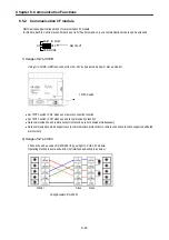
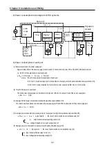
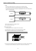
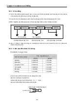
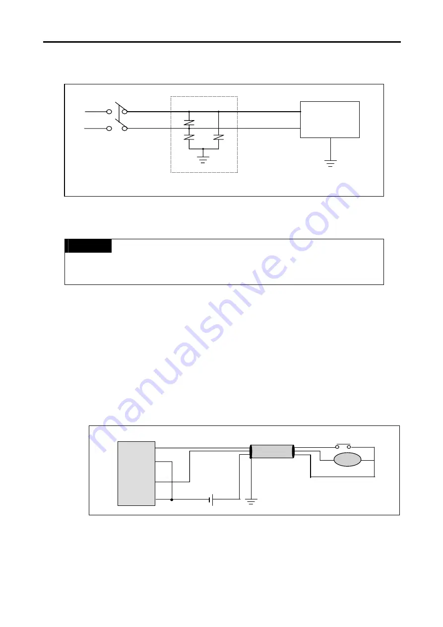
(7) As a measure against very large surge(e.g. due to lightening),connect a surge absorber as shown below.
(8) Use a insulating transformer or noise filter for protection against noise.
(9)
Twist every input power supply wires as closely as possible. Do not allow the transformer or noise filter across the duct.
REMARK
1)
Ground the surge absorber(E1) and the PLC(E2) separately from each other
.
2) Select a surge absorber making allowances for power voltage rises.
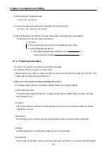
9.2.2 Input and output devices wiring
(1) Applicable size of wire to the terminal block connector is 0.18 to 2
㎟
. However, it is recommended to use wire of 0.5
㎟
for
convenience.
(2) Separate the input and output lines.
(3) I/O signal wires must be at least 80
㎜
away from high voltage and large current circuit wires.
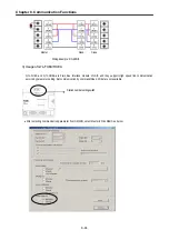
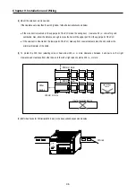
(4) When the I/O signal wires cannot be separated from the main circuit wires and power wires, ground on the PLC side with batch-
shielded cables. Under some conditions it may be preferable to ground on the other side.
(5) If wiring has been done with of piping, ground the piping.
(6)
Separate the 24VDC I/O cables from the 110VAC and 220VAC cables.
(7) If wiring over 200m or longer distance, trouble can be caused by leakage currents due to line capacity.
Refer to the section ’11.4 Troubleshooting Examples.’
E2
PLC
E1
Surge absorber for lightening
Input
PLC
Shielded cable
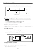
RA
DC
Summary of Contents for GLOFA G7M-DR20U
Page 28: ...Chapter 4 Names of Parts 4 3 2 G7M DRT60U N 3 G7M DT60U N 4 G7M DT60U P...
Page 29: ...Chapter 4 Names of Parts 4 4 5 G7M DR60U DC 6 G7M DRT60U N DC 7 G7M DT60U N DC...
Page 31: ...Chapter 4 Names of Parts 4 6 3 G7M DT40U N 4 G7M DT40U P 5 G7M DR40U DC...
Page 32: ...Chapter 4 Names of Parts 4 7 6 G7M DRT40U N DC 7 G7M DT40U N DC 8 G7M DT40U P DC...
Page 33: ...Chapter 4 Names of Parts 4 8 4 1 3 30 point main unit 1 G7M DR30U 2 G7M DRT30U N 3 G7M DT30U N...
Page 34: ...Chapter 4 Names of Parts 4 9 4 G7M DT30U P 5 G7M DR30U DC 6 G7M DRT30U N DC...
Page 36: ...Chapter 4 Names of Parts 4 11 2 G7M DRT20U N 3 G7M DT20U N 4 G7M DT20U P...
Page 37: ...Chapter 4 Names of Parts 4 12 5 G7M DR20U DC 6 G7M DRT20U N DC 7 G7M DT20U N DC...
Page 38: ...Chapter 4 Names of Parts 4 13 8 G7M DT20U P DC...
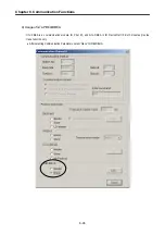
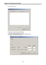
Page 159: ...Chapter 7 Usage of Various Functions 7 52 c Program...
Page 183: ...Chapter 7 Usage of Various Functions 7 76 c Program...
Page 253: ...Chapter 8 Communication Functions 8 27 b When uses Ch 1 Built in RS 485...
Page 356: ...Appendix 1 System Definitions App1 9 6 Position Parameter...
Page 357: ...Appendix 1 System Definitions App1 10 7 High Speed Counter Parameter...


