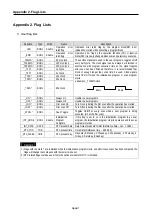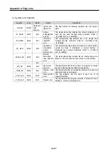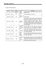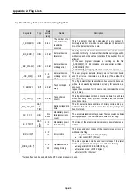
Appendix 1. System Definitions
App1-5
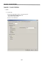
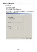
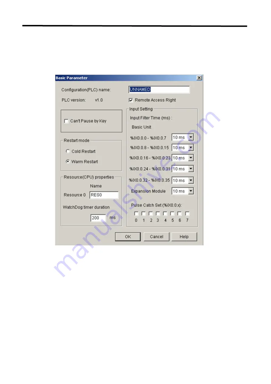
2) Basic Parameter
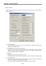
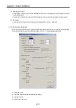
The basic parameters are necessary for the operation of the PLC and used to allocate memory, set the restart mode and
watchdog timer duration, etc
(1)
Configuration(PLC) Name
•
It is a representative name for the PLC system. It is used to designate this PLC system when a network system is
configured using communication modules.
(2)
Enabling/Disabling the control of the PLC via communications
•
This parameter is used to enable or disable the remote control of this PLC system through the FAM or computer link
module, etc. except for the GMWIN. If this parameter has been set to enable, change of the operation mode and
download of programs are available via communications.
(3)
Restart Mode
•
This parameter is used to set the restart mode in the PLC system.
When the system re-starts, one of the ‘cold restart’ or ‘warm restart’ is selected in compliance with the parameter setting.
(4)
Resource(CPU) properties
•
Resource Name is the name that each CPU module configuring the PLC has. When configuring a network system the
name is used to designate each CPU module that is used the system.
•
Only one CPU module can be mounted in the GM7U series, therefore, only the resource 0 is valid.
Summary of Contents for GLOFA G7M-DR20U
Page 28: ...Chapter 4 Names of Parts 4 3 2 G7M DRT60U N 3 G7M DT60U N 4 G7M DT60U P...
Page 29: ...Chapter 4 Names of Parts 4 4 5 G7M DR60U DC 6 G7M DRT60U N DC 7 G7M DT60U N DC...
Page 31: ...Chapter 4 Names of Parts 4 6 3 G7M DT40U N 4 G7M DT40U P 5 G7M DR40U DC...
Page 32: ...Chapter 4 Names of Parts 4 7 6 G7M DRT40U N DC 7 G7M DT40U N DC 8 G7M DT40U P DC...
Page 33: ...Chapter 4 Names of Parts 4 8 4 1 3 30 point main unit 1 G7M DR30U 2 G7M DRT30U N 3 G7M DT30U N...
Page 34: ...Chapter 4 Names of Parts 4 9 4 G7M DT30U P 5 G7M DR30U DC 6 G7M DRT30U N DC...
Page 36: ...Chapter 4 Names of Parts 4 11 2 G7M DRT20U N 3 G7M DT20U N 4 G7M DT20U P...
Page 37: ...Chapter 4 Names of Parts 4 12 5 G7M DR20U DC 6 G7M DRT20U N DC 7 G7M DT20U N DC...
Page 38: ...Chapter 4 Names of Parts 4 13 8 G7M DT20U P DC...
Page 159: ...Chapter 7 Usage of Various Functions 7 52 c Program...
Page 183: ...Chapter 7 Usage of Various Functions 7 76 c Program...
Page 253: ...Chapter 8 Communication Functions 8 27 b When uses Ch 1 Built in RS 485...
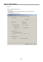
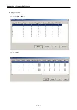
Page 356: ...Appendix 1 System Definitions App1 9 6 Position Parameter...
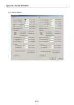
Page 357: ...Appendix 1 System Definitions App1 10 7 High Speed Counter Parameter...


