


Chapter 7. Usage of Various Functions
7-117
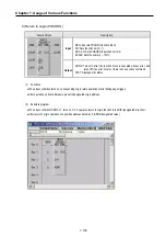
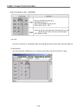
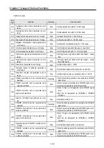
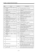
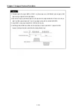
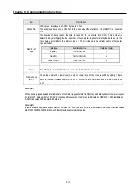
REMARK
1) The rated input for the origin of GM7U is DC 24V.
2) Input points for origin, approximate origin point, and upper/lower limit signal are fixed but, if they’re not used you
able to use them general input point. You can use emergency stop with the command(POSCTR)
3) Positioning phase of GM7U is as follow: Set the input mode of a step mode driver to 1 phase input mode is
determined by rotating direction input.
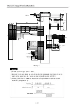
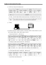
* 2
Analog torque limit
+10V/max. current
Max: 2m
Outer emergency stop
Servo : ON
Reset
PID
Torque Limit
Forward direction position limit
Reverse direction position Limit
*3
*3
RA1
RA2
RA3
Power
3Phase 200VAC
NF
RD
SD
GND
GND
RS
CS
DR
ER
L1
L2
L3
L11
L21
CTE2
D
P
CN1A
PG
13
PP
3
NG
12
OPC
11
COM
9
EMG
15
SON
5
RES
14
PC
8
TL
9
LSP
16
LSN
17
SG
10
SG
20
VDD
3
COM
13
ALM
18
ZSP
19
TLC
6
P15R
11
TLA
12
LG
1
SD
Plate
CN1E
TE11
MR-J2S- A
U
V
W
PE
PE
HC-MF HA-FF
Series motor
U
V
W
E
EMG
24VDC
CN2
B1
B2
SM
2
1
12
TxD
RxD
LG
11
5
15
LG
LG
LG
4
3
14
13
Plate
GND
RS
CS
DR
ER
CN3
A
A
Monitor output
Max 10mA
10k
10k
Personal
computer
Within 2m
Within 2m
MC
Pulse
DC24V
G7M-D(R)T**U(P)
NP
2
P40
P41
Signal
Ch0
Ch1
Direction
P42
P43
Common
COM0 COM1
Common
COM2 COM2
Input 0V
0V
0V
Origin
P04
P06
P05
P07
High Limit
P01
P03
Low Limit
P00
P02
Emergency
Input point
Common
COM0(Input
)
OP
14
LG
1
SD
Plate
DOG
* 1
* 3
failure
zero speed detection
in torque limit
OPP of Servo ON signal
Cutoff by alarm signal
electronic brake
detector
1.2K, 1/2W
1.2K, 1/2W
DC24V
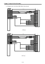
< PNP Type >
Summary of Contents for GLOFA G7M-DR20U
Page 28: ...Chapter 4 Names of Parts 4 3 2 G7M DRT60U N 3 G7M DT60U N 4 G7M DT60U P...
Page 29: ...Chapter 4 Names of Parts 4 4 5 G7M DR60U DC 6 G7M DRT60U N DC 7 G7M DT60U N DC...
Page 31: ...Chapter 4 Names of Parts 4 6 3 G7M DT40U N 4 G7M DT40U P 5 G7M DR40U DC...
Page 32: ...Chapter 4 Names of Parts 4 7 6 G7M DRT40U N DC 7 G7M DT40U N DC 8 G7M DT40U P DC...
Page 33: ...Chapter 4 Names of Parts 4 8 4 1 3 30 point main unit 1 G7M DR30U 2 G7M DRT30U N 3 G7M DT30U N...
Page 34: ...Chapter 4 Names of Parts 4 9 4 G7M DT30U P 5 G7M DR30U DC 6 G7M DRT30U N DC...
Page 36: ...Chapter 4 Names of Parts 4 11 2 G7M DRT20U N 3 G7M DT20U N 4 G7M DT20U P...
Page 37: ...Chapter 4 Names of Parts 4 12 5 G7M DR20U DC 6 G7M DRT20U N DC 7 G7M DT20U N DC...
Page 38: ...Chapter 4 Names of Parts 4 13 8 G7M DT20U P DC...
Page 159: ...Chapter 7 Usage of Various Functions 7 52 c Program...
Page 183: ...Chapter 7 Usage of Various Functions 7 76 c Program...
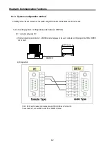
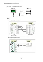
Page 253: ...Chapter 8 Communication Functions 8 27 b When uses Ch 1 Built in RS 485...
Page 356: ...Appendix 1 System Definitions App1 9 6 Position Parameter...
Page 357: ...Appendix 1 System Definitions App1 10 7 High Speed Counter Parameter...


