

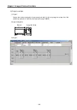
Chapter 7. Usage of Various Functions
7-61
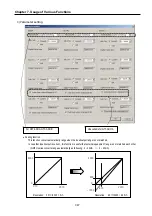
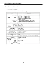
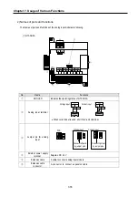
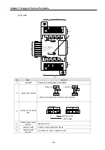
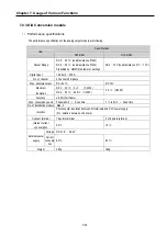
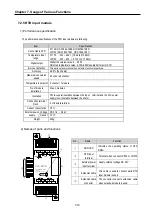
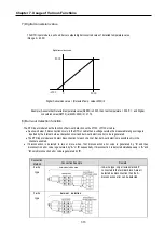
7.2.3 D/A Conversion module
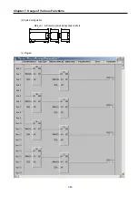
1)
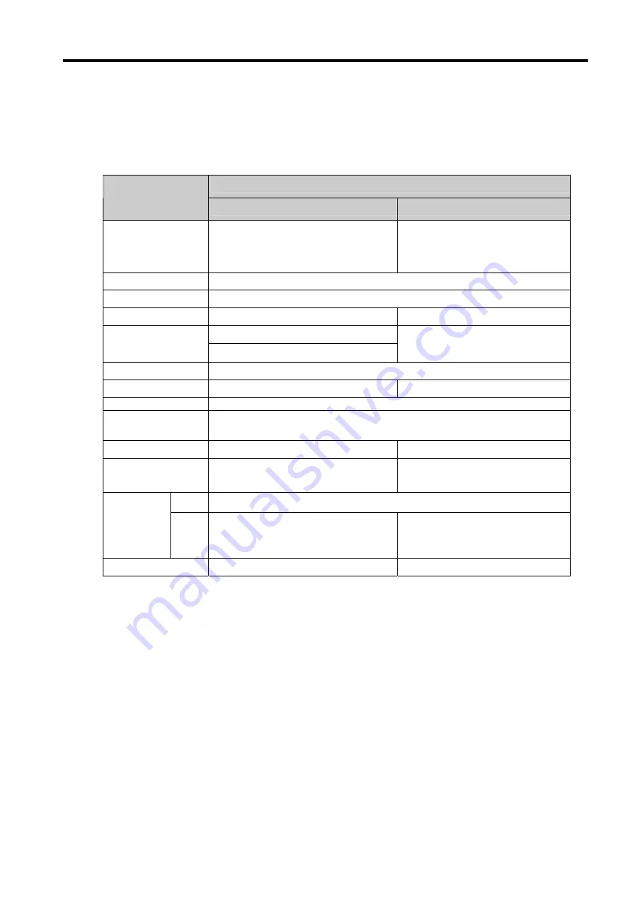
Performance specifications
The performance specifications of the analog output module are following
.
Specifications
Item
G7F-DA2I
G7F-DA2V
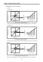
Output Range
DC 0 20
∼
㎃
(Load resistance 510
Ω
)
DC 4 20
∼
㎃
(Load resistance 510
Ω
)
Classified by GMWIN parameter settings
DC 0 10V
∼
(Load resistance 2
㏀
1
∼
㏁
)
Digital input
12 bits ( 0 ~ 4000 )
No. of channel
4 channels/1 module
Max. absolute output
DC +24
㎃
DC 12V
DC 0 20
∼
㎃
: 5
㎂
(1/4000 )
Maximum
resolution
DC 4 20
∼
㎃
: 6.25
㎂
(1/3200 )
2.5
㎷
(1/4000)
Accuracy
±0.5% (Full Scale)
Max. conversion speed
500us/all Ch
+
Scan time
1
㎳
/all Ch
+
Scan time
No. of installation module Max. 3
Isolation
Photo coupler insulation between I/O terminals and PLC power supply
(No isolation between channels)
Connect terminal
16 points terminal
2 of 8 points terminal
Internal current
consumption
20
㎃
15
㎃
Voltage DC 21.6 26.4V
∼
External power
supply
Current
consump
tion
80
㎃
90
㎃
Weight 280g
160g
Summary of Contents for GLOFA G7M-DR20U
Page 28: ...Chapter 4 Names of Parts 4 3 2 G7M DRT60U N 3 G7M DT60U N 4 G7M DT60U P...
Page 29: ...Chapter 4 Names of Parts 4 4 5 G7M DR60U DC 6 G7M DRT60U N DC 7 G7M DT60U N DC...
Page 31: ...Chapter 4 Names of Parts 4 6 3 G7M DT40U N 4 G7M DT40U P 5 G7M DR40U DC...
Page 32: ...Chapter 4 Names of Parts 4 7 6 G7M DRT40U N DC 7 G7M DT40U N DC 8 G7M DT40U P DC...
Page 33: ...Chapter 4 Names of Parts 4 8 4 1 3 30 point main unit 1 G7M DR30U 2 G7M DRT30U N 3 G7M DT30U N...
Page 34: ...Chapter 4 Names of Parts 4 9 4 G7M DT30U P 5 G7M DR30U DC 6 G7M DRT30U N DC...
Page 36: ...Chapter 4 Names of Parts 4 11 2 G7M DRT20U N 3 G7M DT20U N 4 G7M DT20U P...
Page 37: ...Chapter 4 Names of Parts 4 12 5 G7M DR20U DC 6 G7M DRT20U N DC 7 G7M DT20U N DC...
Page 38: ...Chapter 4 Names of Parts 4 13 8 G7M DT20U P DC...
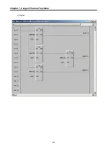
Page 159: ...Chapter 7 Usage of Various Functions 7 52 c Program...
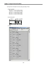
Page 183: ...Chapter 7 Usage of Various Functions 7 76 c Program...
Page 253: ...Chapter 8 Communication Functions 8 27 b When uses Ch 1 Built in RS 485...
Page 356: ...Appendix 1 System Definitions App1 9 6 Position Parameter...
Page 357: ...Appendix 1 System Definitions App1 10 7 High Speed Counter Parameter...


