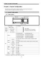
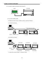


Chapter 2. System Configuration
2-5
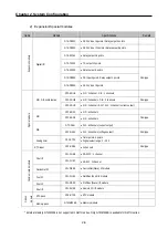
2.2.2 GM7U series system equipment product
1) Main
Unit
Items
Models
I/O Point & Power Supply
Built-in Function
Remark
G7M-DR20U
G7M-DR20U/DC
1) DC24V input 12 points
2) Relay output 8 points
3) AC 85 ~ 264[V]
/DC : DC10.8~26.4V
G7M-DR30U
G7M-DR30U/DC
1) DC24V input 18 points
2) Relay output 12 points
3) AC 85 ~ 264[V]
/DC : DC10.8~26.4V
G7M-DR40U
G7M-DR40U/DC
1) DC24V input 24 points
2) Relay output 16 points
3) AC 85 ~ 264[V]
/DC : DC10.8~26.4V
G7M-DR60U
G7M-DR60U/DC
1) DC24V input 36 points
2) Relay output 24 points
3) AC 85 ~ 264[V]
/DC : DC10.8~26.4V
- High speed counter
1 phase: 100kHz 2Ch, 20 kHz 2Ch
2 phase: 50kHz 1Ch, 10 kHz 1Ch
- Pulse catch: 10
㎲
2 points / 50
㎲
6 points
(IX0.0.0~IX0.0.7)
-
External interrupt:
1
㎲
2 points/50
㎲
6 points
(IX0.0.0~IX0.0.7)
-
Input filter:
0 ~ 1s
(can be designated
with groups)
- PID control
- RS-232C / RS-485
G7M-DRT20U(N)
G7M-DRT20U(N)/DC
1) DC24V input 12 points
2) Relay output 4 points
3) NPN TR output 4 points
4) AC 85 ~ 264[V]
/DC : DC10.8~26.4V
G7M-DRT30U(N)
G7M-DRT30U(N)/DC
1) DC24V input 18 points
2) Relay output 8 points
3) NPN TR output 4 points
4) AC 85 ~ 264[V]
/DC : DC10.8~26.4V
G7M-DRT40U(N)
G7M-DRT40U(N)/DC
1) DC24V input 24 points
2) Relay output 12 points
3) NPN TR output 4 points
4) AC 85 ~ 264[V]
/DC : DC10.8~26.4V
G7M-DRT60U(N)
G7M-DRT60U(N)/DC
1) DC24V input 36 points
2) Relay output 20 points
3) NPN TR output 4 points
4) AC 85 ~ 264[V]
/DC : DC10.8~26.4V
G7M-DT20U(N)
G7M-DT20U(N)/DC
G7M-DT20U(P)
G7M-DT20U(P)/DC
1) DC24V input 12 points
2) TR. output 8 points
3) AC 85 ~ 264[V]
/DC : DC10.8~26.4V
G7M-DT30U(N)
G7M-DT30U(N)/DC
G7M-DT30U(P)
G7M-DT30U(P)/DC
1) DC24V input 18 points
2) TR. output 12 points
3) AC 85 ~ 264[V]
/DC : DC10.8~26.4V
G7M-DT40U(N)
G7M-DT40U(N)/DC
G7M-DT40U(P)
G7M-DT40U(P)/DC
1) DC24V input 24 points
2) TR. output 16 points
3) AC 85 ~ 264[V]
/DC : DC10.8~26.4V
Mai
n u
nit
G7M-DT60U(N)
G7M-DT60U(N)/DC
G7M-DT60U(P)
G7M-DT60U(P)/DC
1) DC24V input 36 points
2) TR. output 24 points
3) AC 85 ~ 264[V]
/DC : DC10.8~26.4V
- High speed counter
1 phase: 100kHz 2Ch, 20 kHz 2Ch
2 phase: 50kHz 1Ch, 10 kHz 1Ch
- Pulse catch: 10
㎲
2 points / 50
㎲
6 points
(IX0.0.0~IX0.0.7)
-
External interrupt:
10
㎲
2 points / 50
㎲
6 points
(IX0.00~IX0.0.7)
-
Input filter:
0 ~ 1s
(can be designated
with groups)
- PID control
- RS-232C / RS-485
-
Positioning function
- 2axes 100 kpps
- Absolute / Incremental positioning
- Single / Repeat operation
- End / Keep / Continuous mode
- Return to origin, JOG, PWM, velocity
control
(N) : NPN TR. output
(P) : PNP TR. output
Summary of Contents for GLOFA G7M-DR20U
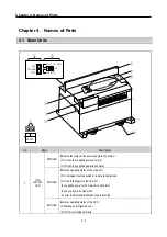
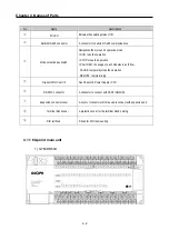
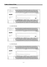
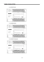
Page 28: ...Chapter 4 Names of Parts 4 3 2 G7M DRT60U N 3 G7M DT60U N 4 G7M DT60U P...
Page 29: ...Chapter 4 Names of Parts 4 4 5 G7M DR60U DC 6 G7M DRT60U N DC 7 G7M DT60U N DC...
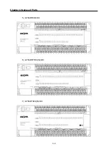
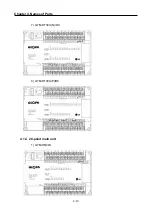
Page 31: ...Chapter 4 Names of Parts 4 6 3 G7M DT40U N 4 G7M DT40U P 5 G7M DR40U DC...
Page 32: ...Chapter 4 Names of Parts 4 7 6 G7M DRT40U N DC 7 G7M DT40U N DC 8 G7M DT40U P DC...
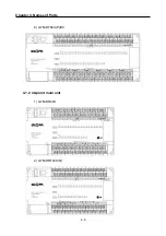
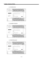
Page 33: ...Chapter 4 Names of Parts 4 8 4 1 3 30 point main unit 1 G7M DR30U 2 G7M DRT30U N 3 G7M DT30U N...
Page 34: ...Chapter 4 Names of Parts 4 9 4 G7M DT30U P 5 G7M DR30U DC 6 G7M DRT30U N DC...
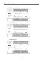
Page 36: ...Chapter 4 Names of Parts 4 11 2 G7M DRT20U N 3 G7M DT20U N 4 G7M DT20U P...
Page 37: ...Chapter 4 Names of Parts 4 12 5 G7M DR20U DC 6 G7M DRT20U N DC 7 G7M DT20U N DC...
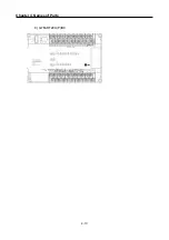
Page 38: ...Chapter 4 Names of Parts 4 13 8 G7M DT20U P DC...
Page 159: ...Chapter 7 Usage of Various Functions 7 52 c Program...
Page 183: ...Chapter 7 Usage of Various Functions 7 76 c Program...
Page 253: ...Chapter 8 Communication Functions 8 27 b When uses Ch 1 Built in RS 485...
Page 356: ...Appendix 1 System Definitions App1 9 6 Position Parameter...
Page 357: ...Appendix 1 System Definitions App1 10 7 High Speed Counter Parameter...


