


Chapter 7. Usage of Various Functions
7-33
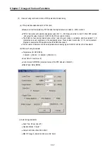
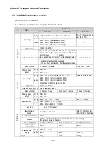
Process
ⓑ
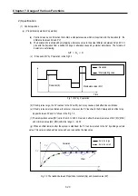
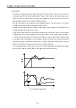
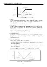
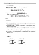
reaction curve method(PRC method).
•
PID parameters are obtained by step response of process.
•
It is useful fo r time 1
st
order time delay system expressed as following
1
+
−
Ts
e
K
Ls
•
Obtained parameters may not accurate if the process can’t approximated to 1
st
order system, In this
case, use relay response method.
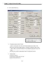
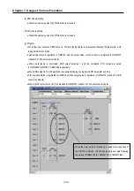
ⓒ
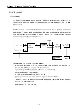
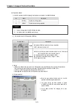
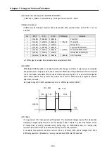
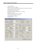
PWM Tuning
PWM (Pulse Width Modulation) is a output method which changes on-off duty of output pulses by
calculated manipulation value. The figure below shows an example of PWM output. Using PWM output,
PID control system can be constructed easily without D/A conversion module and power regulator. The
output can be designated when PWM is selected, but only main unit’s contacts can be used for PWM
output. (The expansion module’s cannot be used.)
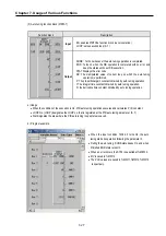
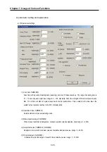
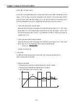
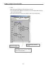
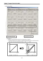
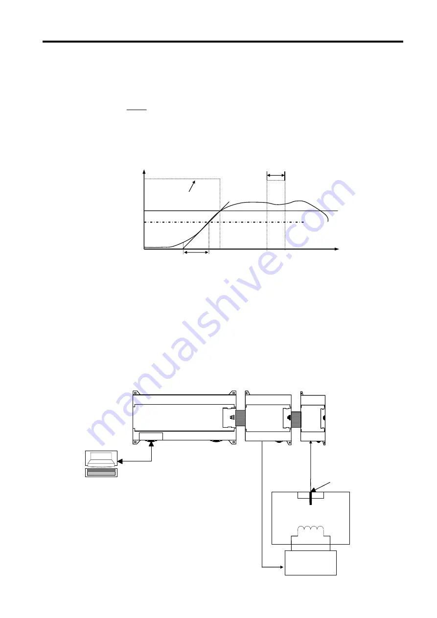
5) Program example
(1)
System configuration
80% of SV
MV
4000
Time delay(L)
63% of SV
Time constant(T)
GMWIN
V4.1 above
RS-232C
TPR
Heater
Electric Oven
(PV: temperature)
(MV: 4~20mA)
GM7U
G7F-DA2I
G7F-
RD2A
Summary of Contents for GLOFA G7M-DR20U
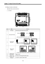
Page 28: ...Chapter 4 Names of Parts 4 3 2 G7M DRT60U N 3 G7M DT60U N 4 G7M DT60U P...
Page 29: ...Chapter 4 Names of Parts 4 4 5 G7M DR60U DC 6 G7M DRT60U N DC 7 G7M DT60U N DC...
Page 31: ...Chapter 4 Names of Parts 4 6 3 G7M DT40U N 4 G7M DT40U P 5 G7M DR40U DC...
Page 32: ...Chapter 4 Names of Parts 4 7 6 G7M DRT40U N DC 7 G7M DT40U N DC 8 G7M DT40U P DC...
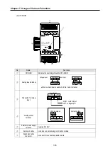
Page 33: ...Chapter 4 Names of Parts 4 8 4 1 3 30 point main unit 1 G7M DR30U 2 G7M DRT30U N 3 G7M DT30U N...
Page 34: ...Chapter 4 Names of Parts 4 9 4 G7M DT30U P 5 G7M DR30U DC 6 G7M DRT30U N DC...
Page 36: ...Chapter 4 Names of Parts 4 11 2 G7M DRT20U N 3 G7M DT20U N 4 G7M DT20U P...
Page 37: ...Chapter 4 Names of Parts 4 12 5 G7M DR20U DC 6 G7M DRT20U N DC 7 G7M DT20U N DC...
Page 38: ...Chapter 4 Names of Parts 4 13 8 G7M DT20U P DC...
Page 159: ...Chapter 7 Usage of Various Functions 7 52 c Program...
Page 183: ...Chapter 7 Usage of Various Functions 7 76 c Program...
Page 253: ...Chapter 8 Communication Functions 8 27 b When uses Ch 1 Built in RS 485...
Page 356: ...Appendix 1 System Definitions App1 9 6 Position Parameter...
Page 357: ...Appendix 1 System Definitions App1 10 7 High Speed Counter Parameter...


